
Question 24: During the oxidation step in the regeneration of fixed-bed catalytic reformers, how does varying the length and oxygen concentration affect the unit performance?
DUNHAM (UOP)
The length of the oxidation period will vary from a minimum of 11 hours up to 24 hours. The timeframe will depend on the amount of platinum agglomeration, surface area, oxygen content, and chloride injection rate. Minimizing the burn temperature during the primary burn will minimize agglomeration. So, if you are dealing with low surface area catalyst, you will need a richer chloride environment, which is a lower hydrogen-in-chloride ratio, when you are in that step.
Historically, oxygen contents were held lower. But recently, these concentrations have been going up as high as 12%. Some of the safety issues have already been addressed. Higher concentration of oxygen increases the rate of metal redispersion. When you get finished with this step, if you have catalyst samplers, you can get a sample of the catalyst. A nice creamy color tells you the oxidation step was done right.
PATEL (Valero Energy Corporation)
Unless time is critical, adding extra time could result in an advantage. Improvements have been noted in catalyst appearance when extending the oxidation period from the typical 11 to 16 hours up to 24 hours. Holding in the oxidation state for up to 36 hours could also be acceptable except that beyond that, there is a little benefit to the catalyst and there is a high risk of increased corrosion in the unit because you are still injecting a lot of chlorides and making up the caustic.
For the oxygen concentration, increasing the amount of oxygen partial pressure will speed up the rate at which the oxidation is complete. Also, a high concentration of oxygen should increase the rate of metal redispersion. Prior to increasing any oxygen concentration beyond the recommended minimum 5%, the compressor configuration should be reviewed because centrifugal recycle compressor with lube oil sealed system may hit the exploding limit with higher oxygen concentration.
CLAY MARBRY (Roddey Engineering Services, Inc.)
That was a good point about the lube oil system and potential ignition of the compressor lube oil. If you get more than 8% oxygen, you can start to see some problems there. We have also seen some coke ignite in the feed effluent exchange section. If you get above 8% oxygen, some harder-to-burn coke, such as graphitic coke, can ignite. The form of this coke can be debated; but in our experience, we have seen coke in the feed effluent exchangers ignite at higher oxygen concentrations.
An additional thought on increasing oxygen concentration: The higher the oxygen concentration you reach during the oxidation step, the longer the purge step will take to reduce the oxygen concentration to acceptable levels before hydrogen introduction in the reduction step.
As far as extending the oxidation step time is concerned, that is a fantastic maintenance hold period if you have an upset or a problem. We have been in regenerations where we have held the oxidation step for multiple days. You run the risk of corrosion, and you are using up caustic the whole time. There is a cost associated with extending the oxidation step, but this is the safest time, for the catalyst, to extend the regeneration.
Year
2015
Process
Question 25: Have you detected any hydrogen chloride slip in the stabilizer bottoms for any gasoline units (isomerization or reformer)? What are your Best Practices to prevent downstream unit corrosion?
DUNHAM (UOP)
Occasionally, isomerization units will slip some HCl or organic chlorides at the bottom of the stabilizer. The key here is having the proper reflux ratio on that tower because you need to keep the partial pressure of the HCl low enough that it will not overheat. So, you need a reflux-to-feed ratio of 0.5 to 0.8 to make sure that this chloride will not go down the stabilizer. We often see some refiners doing an energy audit. So, I will say, “Gee, we could save some energy if we cut the reflux ratio.” When they do the simulation, they see that it does not have the HCl. They do not understand that the HCl will go down the tower. I have seen this on a C4 isomerization unit. A customer sent a lot of chloride over to a sulfuric acid unit. The fractionator was wet, and the whole downstream overhead system was severely corroded. So, you really must be careful about stripping chloride out of the butane product.
PATEL (Valero Energy Corporation)
The HCl or organic chloride slip can occur in the isom stabilizer bottom. The reformer stabilizer operates at a relatively higher temperature, and the HCl should decompose at that condition. However, heavy organic chloride slip can occur from the reformer stabilizer bottom. Just maintaining a sufficient reflux-to-feed ratio for internal traffic in the isom stabilizer can push the HCl into the overhead where it belongs. The recommended reflux-to-feed ratio for the stabilizer is 0.5 to 0.8. However, at our unit, we operate at as low as a 0.25 reflux-to-feed ratio without experiencing any bottom slippage issues. In the reformer stabilizer, no chloride corrosion is expected if a facilitator is installed in front of stabilizer.
ABIGAIL SUP (Johnson Matthey Process Technologies)
Based on Johnson Matthey’s experience while working with various operators of catalytic reformers and isomerization units, ppm levels of chlorides have been detected in the stabilizer bottoms of both units. However, requests for chloride solutions for the stabilizer bottoms stream are more commonly received from catalytic reforming units. The typical chloride concentration reported by operators has been in the range of 3 to 5 ppmw. However, the number of chlorides present in each stream of a particular unit will vary based on operating parameters and unit design.
It is worth highlighting that organic chlorides can also be present and are more difficult to detect. If current testing has indicated that HCl is not detectable in the stabilizer bottoms but downstream corrosion is occurring, it may be that the chlorides are present, but in the form of organic chlorides. Johnson Matthey can coordinate testing, both field and lab, to measure both HCl and organic chloride levels across the unit. This sampling can help determine the number of chlorides present in various streams of a particular operating unit.
In order to prevent downstream corrosion caused by chlorides, chloride guards can be placed in various locations in the flowsheet. Chloride guard beds are an adsorbent and/or absorbent that can be installed to remove chlorides. Depending on the material employed, these beds can be designed to remove both HCl and organic chlorides down to less than 0.1 ppmw. The location(s) of the chloride guard bed(s) will depend on the operator’s issues and preferences. Below is a diagram showing possible locations of chloride guards in a typical catalytic reforming unit.
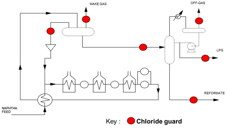
There are three chloride guard locations that will reduce the chlorides in the stabilizer bottoms stream. The most straight-forward choice would be to install a chloride guard directly on the stabilizer bottoms stream. An alternate option would be to install a chloride guard on the unstabilized reformate entering into the stabilizer column. The advantages of this option are that you also protect the stabilizer column itself from ammonium chloride fouling while at the same time removing chlorides from the other product streams exiting the column. This reduces the overall number of beds required if multiple product streams need to be treated. The size of the guard bed for the stabilizer column feed would also be similar to that used solely for the stabilizer bottoms. This means it would provide additional protection with little additional investment required. A third option to consider would be to install a chloride guard on the recycled hydrogen stream. This option would aid in reducing the chloride levels across the entire system, which would include reducing the chlorides exiting with the stabilizer bottoms.
Year
2015
Process
Question 26: What is your Best Practice for packing (material and shape) in isomerization unit off gas caustic scrubbers?
DUNHAM (UOP)
UOP recommends carbon Raschig rings. The key here is to specify to the vendor that this be used for caustic service so that the rings will be formed with the proper binder. If you get the wrong binder, the rings will dissolve. We have a similar service in HF alky units where we use carbon Raschig rings; and there, you have to make sure that the binder is resistant to acid. So, you cannot switch the two. I have seen the carbon Raschig rings ooze out of the tower when a customer bought the wrong binder.
Another material you can use is chemical-grade polypropylene. This is plastic, so it does have temperature limits. If you use this kind of material, you have to be careful not to steamout the tower because this packing is good for the operating temperature of the unit. But if you steam it out, it will melt, and all come out in one piece.
LAMBIE (KBC Advanced Technologies, Inc.)
My experience has only been with the carbon Raschig rings. I have not seen any issues with them in any other sites. My only other comment to add to Daryl’s is that the use of ceramic rings is not recommended because they are not compatible with caustic.
DOMINIC VARRAVETO (Burns & McDonnell)
My question is related to the scrubber. Have there been any comments from the operators of these units with upsets that cause caustic to go backwards into the stabilizer and create plugging in the stabilizer overhead system?
LAMBIE (KBC Advanced Technologies, Inc.)
I have not seen or heard of this happening. Normally there is a check valve in the line to prevent any backflow from the caustic scrubber to the stabilizer.
RICK GRUBB (Chevron Products Company)
We have experienced caustic back-flowing in the overhead receiver drum, so we have installed quick-acting ball valves that activate pressure differential. When the pressure differential gets low enough, it will close the valve.
SCOTT LAMBIE (KBC Advanced Technologies, Inc.)
One-inch OD carbon Raschig rings have been the standard packing material for isomerization unit off gas caustic scrubbers. Use of this packing material has proven to be very effective in minimizing caustic breakthrough and water carryover. Operating the unit per the design circulation flow rates of caustic and water insures proper wetting of the packing material for maximum effectiveness.
The use of ceramic packing material should be avoided as caustic will attack and degrade the material.
Year
2015
Process
Question 27: What is your experience with processing benzene in C5/C6 isomerization units? Have there been any issues with higher reactor exotherms associated with benzene saturation?
DUNHAM (UOP)
UOP’s general guideline is to limit the lead reactor ΔT to 100°F (55°C). This limit is based on our design margins or the heat exchangers around the reactors. That 100-degree limit corresponds to above 5 to 8% benzene in the feed. So, one way to get around that is to recycle or add something to dilute the benzene. Older recycled hydrogen isomerizations will generally have less ΔT than the oncethrough units. We know of some customers who had experience running as high as 110 to 115°F (61 to 64°C) in the lead reactor. A revamp option is to add a benzene saturation reactor upstream of the isomerization reactors.
PATEL (Valero Energy Corporation)
Recycling a stabilizer bottom slip steam back to the feed will dilute the feed, and it will react or reduce reactor delta temperature. The other option, as Daryl suggested, is to install a benzene saturation unit upstream of the reactor.
Year
2015
Process
Question 28: What are your Best Practices for measuring chlorides in LPG streams? What criteria do you use to determine when to change LPG chloride treater media?
KEADY (Technip)
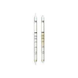
There are three methods for measuring chlorides in LPG streams: UOP 910, UOP 930, and Dräger 2.0.2/A. I have a nice little illustration. You must have proper maintenance of your sampling stations and also of your sampling bombs. For Best Practices, use a sample point a few places within the absorber bed and sample periodically for chloride right through. This frequency will allow historical comparisons. Also, identifying any feed contaminants will help predict the remaining life of the bed.

PATEL (Valero Energy Corporation)
Chloride monitoring in the liquid LPG stream is difficult in the refinery. Typically, the next downstream gas phase stream, which is originating from the liquid stream, can be tested for the chlorides like stabilizer overhead. However, that is not an option for the LPG stream.
One of the best areas monitored is the chloride in the LPG stream. LPG chloride treater chloride content can be estimated through a reformer chloride balance. A reformer chloride balance is achieved when all of the chlorides are accounted for. The reformer releases chlorides into the hydrogen and into the reformer stream. Tracking those values for the hydrogen net gas and the liquid at the stabilizer overhead can eventually allow you to create a reformer chloride balance, as Emerson said. The reformer chloride balance can produce the amount of chlorides at the inlet of the LPG treater. Chloride intake at the LPG treater inlet is estimated based on the balance and can be used in conjunction with the review of the past spent absorbent analysis. A determination can be made as to the appropriate time to make the changeout on the absorbent without experiencing any breakthrough.
JAY RICHERT [(Marathon Petroleum Company (MPC)]
I am just wondering if the panel could suggest the traditional services within a refinery where chloride treatment is necessary. And then, are you aware of any non-traditional stream locations that have been treated in refineries in order to manage overall chloride problem at the site?
LAMBIE (KBC Advanced Technologies, Inc.)
The most common application of chloride treaters is on the net gas stream where the hydrogen is used in many downstream units. In liquid service, the common locations in the reforming unit are the inlet to a stabilizer column or the LPG from the stabilizer column. In some instances, chloride treatment of the stabilizer bottoms may be necessary, depending on where that stream is routed. Some chloride issues may result from poor desalting operation.
RATHING SABAPATHI [Kuwait National Petroleum Company (KNPC)]
The question is not related to this. Is anyone looking to produce TAME from isoamylene or isopentane? Does anyone have any outlook on this issue as to whether it is economical to produce economics or TAME for more gas? Does anyone have any units here? We have surplus isopentane. We are exploring the possibility, so we would like to see if there is an opening.
BURTON (UOP LLC, A Honeywell Company)
Our TAME unit went away when MTBE (methyl tertiary butyl ether) units went away.
LAMBIE (KBC Advanced Technologies, Inc.)
There are several TAME units processing C5 olefins in South America.
FRY (Delek Refining)
Make sure to watch the reformer off gas. We have a cryogenic recovery plant for our refinery off gases, and we make sure to put a chloride guard bed in our dryers. We do not test for chlorides frequently, but we know we get some there.
ABIGAIL SUP (Johnson Matthey Process Technologies)
Many operators do struggle when trying to accurately measure the level of chlorides in LPG streams. The Best Practice is to send LPG samples to a lab that has liquid-phase chloride testing capabilities for analysis of both HCl and organic chlorides. Some locations may have these facilities onsite, while others may require the operator to send samples to a third-party lab for independent analysis.
When sampling for chlorides, care should be taken to choose the appropriate sample container. Chlorides, similar to sulfur, have a tendency to “disappear” in the sample container. A suitable lining in the container can help ensure that the level of chlorides is accurately measured during analysis. Also, the chosen sample container should be suitable for vapor samples, commonly referred to as a “sample bomb”. The sample will likely contain a mixture of both liquid and vapor. Some have found it can be difficult to ship LPG samples offsite. Johnson Matthey can help coordinate sampling, so it may also be worthwhile to check if your catalyst supplier also offers assistance.
An alternate option to consider, if liquid phase chloride testing capabilities are not available, is to analyze the LPG sample in the vapor phase. This can be accomplished by flashing the sample into a sample bag. The flashing should be performed under a laboratory hood or other means of ventilation, while taking all proper safety precautions. It is important to ensure that the sample is fully vaporized so that an accurate measurement can be obtained. In certain cases, this may require some form of additional heating. Once the sample is in the gas phase, detector tube technology can then be used to determine the concentration of chlorides present. Keep in mind the concentration results using this method will be in ppmv (parts per million by volume). It is recommended to convert the concentration back to ppmw as is customary for liquid applications. Also, care should be taken to measure both HCl and organic chlorides as some LPG streams may only have organic chlorides present.
To determine when an LPG chloride treater/guard bed should be changed, a routine sampling protocol could be established. This sampling can include periodic measurement of the chloride concentration on both the inlet and the outlet of the chloride treater/guard bed. The inlet sample analysis would allow for calculation of the expected saturation of the chloride media. The amount of chloride that can be absorbed prior to breakthrough can be estimated based on the expected capacity of the material for a particular application. The expected capacity can be provided by the absorbent supplier. The outlet sample analysis would confirm whether or not a breakthrough has occurred.
As sampling can be cumbersome, another option would be to only take baseline chloride measurements and then calculate the life of the bed based on the expected capacity, as discussed above. The baseline chloride concentration and projected flowrate across the bed over time can be used to calculate the expected life of the bed. Changeout can then be scheduled to occur during a downtime that is close to the time breakthrough is expected to occur.
GINGER KEADY (Technip)
Three methods [used?] to analyze the chlorides in LPGs:
-
UOP 910 method for the organic chloride: This method is for determining total chloride in gaseous hydrocarbons or liquefied petroleum gas (LPG) at concentrations ranging from approximately 1 to 1000 mg/mL (milligrams per milliliter) for gas or mass-ppm for LPG (liquefied petroleum gas). Except for fluoride, other halogens present are calculated as chloride. Chloride cannot be determined quantitatively if sulfur is present at concentrations greater than approximately 1 mass-%.
-
UOP 930 method for the total chloride (but Axens has no feedbacks regarding this method): This method is for determining the sum of organic chloride and hydrogen chloride (HCl) in LPG and refinery gas streams at concentrations ranging from approximately 0.02 to 1000 mass-ppm (mg/kg) for LPG samples or 0.02 to 1000 ng/mL for gas samples. Other halogens present are determined as chloride.
-
Dräger Tube Chlorine 0.2/A:

Year
2015
Process
Question 29: What are the likely causes for temperature excursion events in a hydrogen plant?
EPSTEIN [Flint Hills Resources, LP (FHR)]
Hydrogen plant temperature excursions are possible in several of the catalyst vessels and are usually observed in association with the water/gas shift reaction. During normal operation, the high, medium, and low temperature shift reactors display an exothermic reaction. Changes to feed quality can increase this exotherm and cause the operating temperature to exceed the maximum allowable working temperature. A critical alarm on a high reactor discharge temperature is typically used to protect against this condition, with precursor alarms as needed. A similar exotherm is observed during the reverse water/gas shift reaction over the nickel catalyst in the methanator, which can increase under a change in feed quality. The exotherm generated by this reaction is significant enough that commonly occurring initiating events, such as the CO2 (carbon dioxide) removal system pump tripping, can cause the excursion. An SIL (safety integrity level)-rated system is typically used to isolate and depressurize the methanator if an excursion is detected.
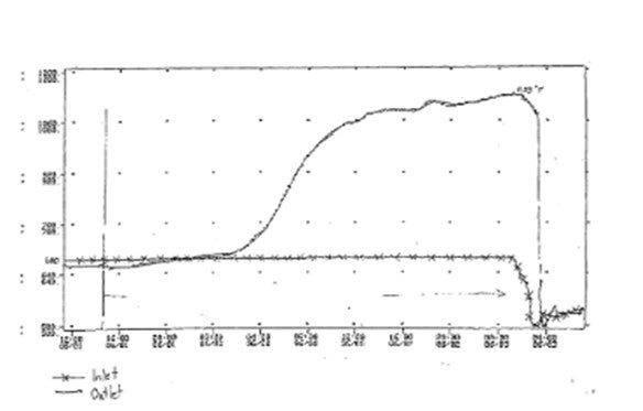
I have personally observed an unexpected temperature excursion when starting up a combined feed pretreatment system. This catalyst combines the qualities of the hydrotreating and desulfurization beds into a single media and contains nickel, molybdenum, cobalt, and zinc oxide. That is what I am trying to show in this chart. Green is the top bed temperature; blue is the bottom bed temperature. We only had two TIs (temperature indicators). Yellow is our hydrogen recycle flow. So during startup, the natural gas feed was introduced, along with very high hydrogen recycle flow, at normal operating temperature and pressure. The unit operating procedure specified for the hydrogen recycle flow to be started at full expected flow rate, followed by ramping up the natural gas slowly. So we went to full-hydrogen rate right away. Under these conditions, it is believed that the hydrogen, CO2, and natural gas reacted exothermically through the reverse water/gas shift reaction similar to the methanator.
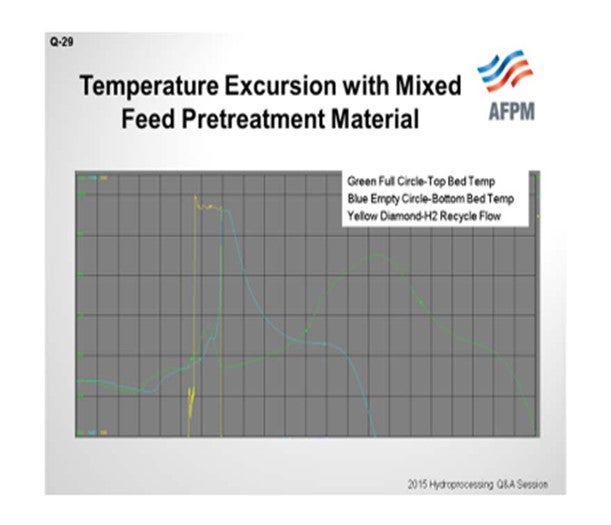
In addition, the catalyst was very dry after prolonged nitrogen circulation, and it is believed that the water generated by the reverse reaction was absorbed by the catalyst causing it to heat up, which initiated a reduction reaction that lead to the temperature excursion. Stopping the hydrogen flow discontinued all of this, and we are able to get back down to a safe level. According to the supplier, this was the first observation of such an issue with this material.
WRIGHT (Hunt Refining Company)
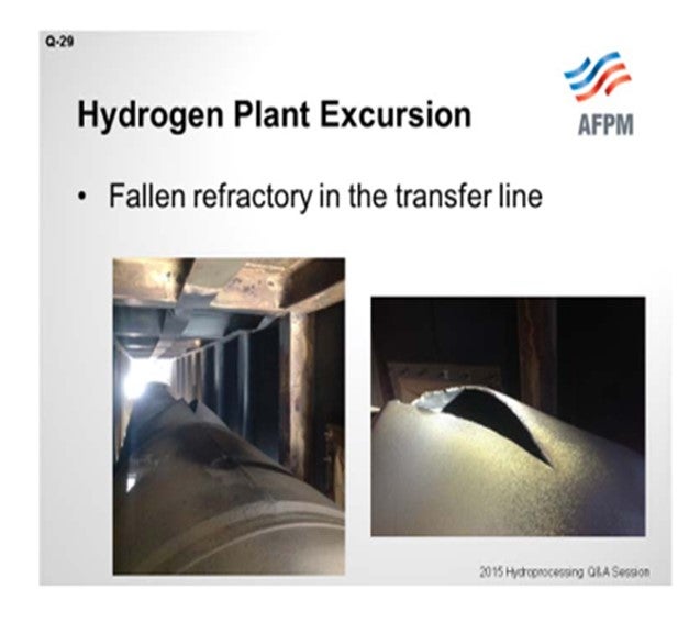
We approached the question from a different angle. We have recently had a temperature excursion which was caused by falling refractory in our transfer line. The transfer line is the pipe in between our reformer box and our first waste heat boiler. The line consists of a metal shell with refractory on the inside. The top portion of the refractory fell, allowing the hot syngas access to the metal shell; and soon, the line developed a fish mouth rupture resulting in what you see in the picture. Fortunately, no one was hurt. There were mainly cosmetic damages on the underside of the heater. So that was a recent event for us.
Other than that, in the past we have just had out-of-the-pipe issues: leaky flanges around some feed heat exchangers. We have had leaks around our PSA (pressure swing adsorber) valves, which caused fires. And one time, we had a fire caused by corrosion and erosion from attemperator water that was used to control the inlet temperature to a shift converter.
MORELAND (Valero Energy Corporation)
In Valero, we have experienced high bed temperatures in hydrogen plants in the high-temperature shift reactor due to failure of the control system or control valve in the upstream process gas boiler that resulted in high inlet temperatures. Additionally, the catalyst was very dry upon startup, and the heat of absorption caused temperatures of over 1200°F to be recorded. In the methanator, as Paul mentioned, we have also had an issue with a failure in the upstream CO2removal system. No catalyst damage was observed in that experience.
EPSTEIN [Flint Hills Resources, LP (FHR)]
We have not yet talked about pre-reforming catalyst. That catalyst is not used at Flint Hills Resources, so I would like to open that up, if anyone has any comments on pre-reformers.
MIKE ADKINS (KP Engineering, LP)
I know this is not directly related to excursions in the reactor. But as far as temperature excursions, in general, from the safety standpoint, it was kind of mentioned by Mr. Epstein on your cooling system looking at the steam generators. Obviously, in one particular plant I experienced. the failure of some of the safety systems. The Number 1 process steam generator blew out because it ran out of water. So definitely, keep in mind that you should be looking at the level instrumentation and safety practices.
JASON SCHMALTZ, NICK MUSICH, and RAJU NATARAJAN (Linde Engineering North America Inc.)
There are a few areas in the hydrogen plant where a temperature excursion is more likely and automated controls/shutdowns should be put in place to mitigate risk. The temperature excursion strategy should be confirmed during a HAZOP (Hazard and Operability) study with the proper risk matrix specific to the client’s site conditions and risk tolerance. The following is a summary of the likely causes for temperature excursion organized by plant area.
HYDROTREATING/DESULFURIZATION
Change in Feed Gas Composition: Increase in unsaturated bonds (e.g., olefins in refinery gases) or CO (carbon monoxide) levels can lead to a temperature spike in the feed gas as it passes through the desulfurization facilities.
Leading Cause: Unexpected change in feed composition is a more likely event at a facility that has multiple feeds from different sources that are constantly changing based on upstream plant performance. Upstream analytical tools can be used to determine if there is a potential feed composition issue and can set the plant to low fire prior to temperature excursion event. This does not necessarily need to be analyzer-based but can be based on a reactor temperature/pressure setting, for example. At a minimum, temperature should be monitored at the outlet of these facilities with proper alarm and/or shutdown systems in place. This does not mitigate the event. The proactive strategy will be mostly based on upstream product disposition criteria management.
New Phenomenon: Oxygen in natural gas from fracking can result in elevated levels of oxygen as compared to typical pipeline-quality natural gas. Although the levels are still relatively low, they can result in an exotherm across the hydrotreating catalyst.
REFORMING
Loss of Hydrocarbon Feed: Rapid loss of hydrocarbon feed can halt the endothermic reaction occurring in the reformer tubes faster than the temperature controls of the reformer are tuned to react. This will result in the steam flowing through the tubes to heat up rapidly and overheat the reformer tubes.
Leading Causes: 1) Loss of feed compression, 2) loss of supply natural gas supply, and 3) failed flow control, the most likely of which is loss of feed compression. Of course, the reformer should be equipped with high-temperature protection for both the process and firebox, but the proper strategy would include controls to mitigate the temperature excursion. Establishing strategies for shutting down preemptively on low flow or tying compressor suction pressure to a plant rate override are both viable with the most straight forward approach being to shut down the plant to low fire conditions on low hydrocarbon flow.
Poisoning/Coking can result in localized hot spots and eventual reformer tube rupture.
Leading Causes: 1) Sulfur or other poisoning, 2) low steam-to-carbon ratio, 3) change in hydrocarbon feed composition, 4) olefins, 5) localized high temperatures due to flame impingement or other furnace performance issues, and 6) deactivated catalyst due to aging are all likely causes of poisoning/coking. Temperatures and pressures around the reformer and furnace should be monitored with appropriate alarms and shutdowns implemented. The reformer should be regularly visually inspected for hot spots and burner operation.
WATER/GAS SHIFT REACTION
High Reaction Rate in Shift Reactor: Sudden increase in shift reaction rate can result in high-temperature excursions. The risks are greater in low and medium temperature shift converters.
Leading Causes: 1) Spike in CO composition, 2) high temperature at inlet, and 3) low steam-to-carbon ratio are the main culprits for high reaction rate in the shift reactor. Feed composition to the shift reactor is highly dependent on reformer operation stability and unit feed composition, especially for feeds other than natural gas. Regular feed sampling schedules should be part of operation practices and understanding of upstream units and when to preemptively reduce or cut feed completely should be understood. Additionally, inlet temperature should be managed based on CO slip indicated over long-term monitoring reports. This temperature should be set as low as possible based on expected methane slip versus actual. This strategy will reduce the chance of runaway reaction occurring. Additionally, alarms and shutdowns can be put in place based on inlet/outlet/delta temperature for the reactor to help mitigate the risk.
COOLING CIRCUIT
Loss of Integrated Cooling: Depending on how integrated the cooling system is with the rest of the plant, a fast reaction to an upset in one part of the plant could translate into significantly less heat sink available in an integrated exchanger. This could result in temperature excursion if the integrated exchanger accounts for a significant portion of the cooling duty.
Leading Cause: Compensation for level fluctuation in steam drum or deaerator is the most common cause. The best mitigation for this is to pay special attention when tuning level controllers that are tied to the cooling circuit water flows. The level controllers should react very slowly so as not to reduce flows significantly during some sort of level upset (there are many root causes for this). It will take operating the plant for a few weeks to determine what tuning parameters make sense long-term. Additionally, overdesigning the cooling section for higher design temperatures can provide some additional assurance that a temperature excursion will have minimal consequence to the equipment. This is typically at a marginal cost increase since this section is already cool enough where stress values for material of construction are only minimally impacted, if at all. Obviously, temperature measurement/alarms/shutdowns should be implemented on the syngas product.
METHANATOR
Feed Contamination: It is common to have a methanator in the old-style, pre-PSA hydrogen plants to convert the low levels of CO (up to 0.3%) and CO2 [up to 200 ppmv (parts per million by volume)] to methane. Methanation is an exothermic reaction and could run away if excessive CO (due to malfunction/misoperation of the low temperature shift reactor) and/or CO2 (due to malfunction/misoperation of the CO2 removal system).
Leading Causes: High CO and/or CO2 in the methanator feed usually create the problem. Typically, a shutoff valve and a vent valve are provided in the feed line with a temperature probe in the first one-third of the section of the bed to detect a rate in temperature rise. A rapid temperature rise will shut the feed valve and vent the syngas to the flare.
TURNAROUND/MAINTENANCE
Oxygen Ingress into Piping/Equipment: Exothermic reaction with hydrogen or hydrocarbons can result in equipment failure due to temperature excursion.
Leading Causes: Improper purging and purge contamination may occur, so proper procedures must be followed.
LOSS OF HYDROCARBON FEED
Rapid loss of hydrocarbon feed can halt the endothermic reaction occurring in the reformer tubes faster than the temperature controls of the reformer are tuned to react. This will result in the steam flowing through the tubes to heat up rapidly and overheat the reformer tubes.
GOPI SIVASUBRAMANIAN (Amec Foster Wheeler)
Temperature excursion events could occur in the HDS (hydrodesulfurization) reactor or in the methanator reactor. Processing higher olefins than the unit is designed for can cause temperature excursions. Less frequent causes are CO2, CO, and oxygen, in that order. Higher CO slip/inlet temperature will cause the methanator reactor to have temperature excursions.
SUE SIMPSON (Johnson Matthey) Temperature excursions can occur in each section of the hydrogen plant for a variety of reasons. Operating issues that can cause temperature increases in the purification, reformer, and shift sections should be avoided as costly damage can occur.
First, in the purification section, a temperature excursion can occur if olefins are present in the feed. The HDS catalyst is also an effective olefin hydrogenation catalyst. The olefin hydrogenation reaction is significantly exothermic and should be considered in the HDS design. If the olefin level will cause the HDS bed to exceed the maximum recommended catalyst temperature, a more active catalyst that reacts at lower temperatures and increases the operating temperature window should be utilized.
Hydrocracking, a very exothermic reaction, has also been observed over HDS catalysts. The risk of hydrocracking increases when the HDS bed temperature exceeds the maximum recommended level for a specified feed, the feed has a very low total sulfur level, or the catalyst has been exposed to high levels of hydrogen. In situations with increased risk, presulfiding the HDS catalyst may be necessary.
In addition, CO and CO2 can methanate on HDS catalysts if the operating conditions and state of the catalyst are conducive. The consequences of the resulting exotherm can be severe, and conditions under which methanation can occur should be avoided. This is achieved by selecting the appropriate catalyst type, depending on the level of carbon oxides in the feed gas. CoMo (cobalt molybdenum) HDS catalysts have a greater tendency to promote methanation reactions whether sulfided or not; however, NiMo (nickel molybdenum) HDS catalysts do not promote methanation when sulfided.
Second, in the reformer, the steam reforming reaction is highly endothermic. If less reforming occurs, the temperature will increase. Feedstock purification is key to ensuring an active reforming catalyst. Sulfur, chlorides, or other heavy metals can poison the catalyst resulting in less reforming and increased temperatures. This can then lead to carbon formation which further reduces catalyst activity. Carbon formation can also be effected by low steam, heavy feed, and burner flame impingement.
In addition, increased temperatures may be the result of reduced flow. Tube blockage or scale can reduce flow causing less reforming and increased temperatures. During transient conditions, flow is typically lower than normal operation making the reformer more vulnerable to temperature excursions. At low flows, less heat load is required which can result in overfiring. Compositions and flows used for instrument calibration may vary during transient conditions resulting in inaccurate measurements. In addition, the heat leak from the temperature measuring point to the tube exit will increase at low flow rates. Typically only inlet and outlet temperatures can be measured, and there is not sufficient manpower available during startup to visually inspect the reformer tubes. These factors can result in temperature increases in a reformer.
A useful tool to monitor the reformer is a multipoint thermocouple called a CatTracker™. This device measures the process gas temperature throughout the tube. The measuring points are individually specified and uniquely designed for a specific plant. The CatTracker™ provides continuous online monitoring with tube temperature profiles available in real time. Determination of the tube temperature profile provides a more accurate prediction of the carbon formation zone. This increases the ability to avoid catalyst steaming and lost production as a result of carbon formation. The installation of trips based on these process gas temperatures can also prevent costly reformer damage. The CatTracker™ is a tool that can aid in the optimization of reformer operation and help determine when catalyst changeout is required.
Finally, in the shift section of the hydrogen plant, temperature excursions can be observed. If a high-temperature shift (HTS) catalyst is exposed to dry nitrogen circulation prior to startup for an extended period, possibly due to refractory curing or a delayed startup, the catalyst surface can be dehydrated. The subsequent rehydration with steam addition is very exothermic.
Medium temperature shift (MTS) and low temperature shift (LTS) catalysts must be reduced prior to plant operation. The reduction is completed with hydrogen and is exothermic. The concentration of hydrogen must be controlled to prevent temperature excursions. When the reduction appears to be complete, a soak period is initiated at a substantially higher hydrogen level. A temperature increase may be observed if unreduced catalyst is still present.
Temperature excursions can occur for a variety of reasons in a hydrogen plant. Understanding the causes can optimize performance and avoid costly damage.
CHAD TAYLOR (Haldor Topsoe, Inc., Inc.)
The main causes for high-temperature excursion events in a hydrogen plant are hydrocracking over the HDS catalyst, runaway during an LTS reduction, and runaway in a methanator from CO2 absorber carryover/failure.
Hydrocracking over HDS Catalyst: Hydrocracking in an HDS reactor can take place in situations where a fresh CoMo/NiMo catalyst is exposed to a hydrogen-rich off gas, with little or no sulfur, at an operating temperature of 600°F or higher. This occurs when the unsulfided CoMo/NiMo oxides are reduced to base metals after being operated for an extended period of time in the hydrogen-rich gas. The resulting reduced catalyst is active for hydrocracking, which is an exothermic reaction. The risk of hydrocracking increases with higher temperature, carbon number, hydrogen partial pressure, and the duration of time of exposure to these conditions. Hydrocracking results in an uncontrollable temperature runaway because the heat produced from the cracking leads to further cracking and even more heat, and so on. This will damage the catalyst and possibly even the HDS vessel. The graph below shows how quickly and how hot an HDS runaway reaction can get.
It should be noted that once a catalyst with hydrotreating functionality has been exposed to ppm levels of sulfur; it is very difficult to reduce the metal sulfides to base metals and create a hydrocracking functionality. In other words, we have never seen an issue during operation, only in connection with fresh catalyst during the initial startup phase.
LTS Reduction: LTS catalyst is delivered in oxides form and needs to be reduced with hydrogen in a carrier gas to be activated according to the following reaction:
CuO + H2 Cu + H2O + HEAT
This reaction is highly exothermic. The reduction is carried out at a specific inlet temperature, and the hotspot temperature is carefully controlled by adjusting the hydrogen concentration in the carrier gas. There is only a small risk of a runaway when using nitrogen as the carrier gas. However, it can happen if too much hydrogen is injected to the reduction loop or if hydrogen or CO- containing gases leak into the reduction loop. Many plants will, however, use once-through natural gas where there is a potential for a runaway reaction due to cracking of the methane or higher hydrocarbons at temperature above 450°F. The hydrogen released from cracking the hydrocarbons will further reduce the catalyst resulting in even more heat, cracking, and hydrogen. The result is a runaway reaction.
As mentioned, a runaway can occur if the hydrogen is increased too quickly and/or not monitored closely or if process gas is leaking in, which increases the hotspot temperature to the point where the cracking begins. The factors affecting the cracking temperature include the amount and type of higher hydrocarbons in the natural gas stream and the pressure of the LTS reactor. A runaway during an LTS reduction will cause damage to the catalyst resulting in shorter run-lengths and/or catalyst replacement and could possibly damage the vessel as well.
If the hydrogen is carefully increased and all of the parameters and procedures are closely followed, then the risk for a runaway is extremely low. Haldor Topsoe, Inc. uses our proprietary TopsafeTM portable hydrogen analyzer. This analyzer provides real-time continuous display of the hydrogen concentration in the carrier gas. Real-time monitoring allows us to bring the concentration up quickly and safely without having to rely on the local lab or a portable GC (gas chromatography) machine, which can require up to 30 minutes or longer to obtain results. You will notice the compact setup in the picture of the TopsafeTM analyzer and setup below:
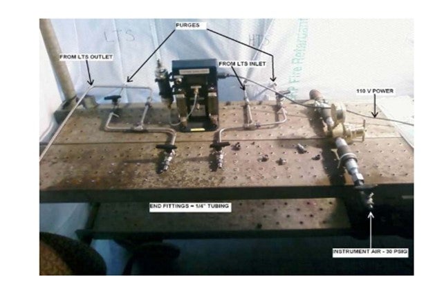
The TopsafeTM analyzer is very reliable and easy to use, and its accuracy is extremely high. The TopsafeTM analyzer is the only online analyzer in the market place for this use.
Methanator CO2 Excursion: The purpose of the methanator is to convert CO and CO2 to methane (reverse reactions of the steam methane reformer). The reactions are:
CO +3 H2 CH4 + H2O + HEAT
CO2 +4 H2 CH4 +2 H2O + HEAT
For every 1 vol% (volume percent) of CO2 converted, there is an increase in temperature of approximately 108°F. At the exit of the LTS vessel, the process gas will have between 15 and 19 vol% CO2, which would result in an exotherm of 1600 to 2050°F. This is obviously unacceptable, so the CO2 is removed in an amine liquid absorption process. If the absorber is underperforming, then it can lead to an increased exotherm across the methanator. If the absorber is not adequately removing the CO2, it will lead to a rapid temperature excursion which is usually not stopped until equilibrium is established around 1500°F. To avoid catalyst and/or vessel damage, most plants have both a high temperature, and a high rate of temperature increase trip which reroutes the process gas to a flare or vent.
Year
2015
Process
Question 30: What factors influence your decision to conduct air versus inert reactor entry for catalyst changeout? For, what methods do you use to avoid stress corrosion cracking?
WRIGHT (Hunt Refining Company)
For us to enter a reactor that is under an inert atmosphere, the conditions need to warrant it, such as when there are large amounts of pyrophoric material still present, when a specific job is required, an old catalyst needs to be vacuumed out for sampling purposes, or if there is filtration material on top that requires removal in order to allow the catalyst below to dump freely. What we have had at times is an encrusted catalyst layer that needs to be jackhammered out in order to be removed or if we have to disassemble a bed distribution tray. Those are some of the reasons why we would enter inertly.
For reactor entry in a fresh air environment, no benzene or high LEL (lower explosive limit) must be present. We generally require this type of atmosphere when an internal inspection is needed.
The second part of the question asked about methods to avoid stress corrosion cracking, or SCC. As a review, SCC occurs when you have a mechanical stress, plus a corrosive environment, that leads to a crack. There are several different types: chloride, polythionic, caustic, sulfide, and others. I will just focus on those first two.

When we have tried to combat those problems, we utilized a soda ash solution which we would apply to the internal surface of the reactor either by spray washing or by simply filling up the vessel. The slide lists a few documents that may be helpful: API (American Petroleum Institute) 571, as well as these other two NACE (National Association for Corrosion Engineers) reports.
EPSTEIN [Flint Hills Resources, LP (FHR)]
The decision between air and inert entry at Flint Hills Resources Pine Bend Refinery comes down to whether or not the reactor vessel has internal hardware and whether an inspection of the vessel for mechanical integrity is necessary. If the shutdown is only to change catalyst and the reactor has only a bottom outlet collector, then the bed is kept inert during the removal and loading processes. For multi-bed reactors or those reactor vessels that require internal vessel inspection, the catalyst is removed under an inert atmosphere. The vessel and its internals are then washed using a soda ash solution via a top-down spray system with several passes and additional focus on the tray areas. The atmosphere is then turned over to air.
MORELAND (Valero Energy Corporation)
In Valero, we make the decision on air entry versus inert entry on a case-by-case basis for each reactor. Typically, we favor air – as the other panelists have said – when there is internal inspection to be done, though it does require an extra atmosphere change. We typically recommend air entry for all hydrocrackers, but we do not require it of our plants. As far as the soda ash washing, guidance from our metallurgist has been that soda ash washing is not needed unless the reactor had seen temperatures above 825°F for an extended period of time. Many of our reactors still soda ash wash even so, just for an extra measure of safety. Inert entry is quicker. It is one less atmosphere change to do. We find that work productivity during inert entry inside the reactor is almost as high as work productivity in air with a good catalyst contractor.
PEDERSEN (UOP LLC, A Honeywell Company)
I encourage you, if you are interested in more details on avoiding stress corrosion cracking, to please check out the answer to Question 36 from last year’s discussion.
DANIELLE OTWINOWSKI (UOP LLC, A Honeywell Company)
Because of the safety concerns with the nitrogen purge and the fact that soda ash washing can be partially ineffective, depending on the solution and how it is applied, to completely eliminate the polythionic acid stress corrosion cracking issues, UOP will be offering a new metallurgy option in conjunction with Nippon Steel & Sumitomo Metal/Mitsui. This metallurgical solution would be for all reactor section components that currently require austenitic stainless steel metallurgy. It is a subset of 347LN which uses patented trace stabilizers to completely eliminate the need for neutralization or soda ash washing. In addition, this new metal does not require thermal heat stabilization during fabrication, which it is an added benefit.
Year
2015
Process
Question 31: What are your current safe practices for sour water monitoring? What are your preferred analytical methods/sampling frequency used to measure NH3/NH4HS (ammonia/ammonium bisulfide)?
McARTHUR (Phillips 66)
The primary concern with sour water sampling is exposing operators to H2S and ammonia, which will evolve off the liquid as it is collected into the sample bottle. Typically, most of our plants would take an approach of ensuring that the operator pulling the sample was in supplied air. This is our most common practice, but it tends to be a little cumbersome. Sometimes it takes some prior planning and operator availability, so it tends to lead to an inconsistent frequency of sampling.
Our preferred approach is to move to engineered sampling stations. This approach would incorporate a closed-loop supply of the sour water. We vent the sample away from the operator. Typically, the liquid sample will be running into the blowdown system. The sample bottles would be sealed with a septum, which is pierced by a sample delivery needle, as part of the sample station. The sample bottle itself is also vented away from the operator through secondary tubing. These bottles do require warehousing, perhaps of something that is not currently in stock at the plant.
Septum covers are also required for the tops of the bottles. Several of our plants are now using some analyzer capability for the sour water. These are plants which typically run against their ammonium bisulfide limits, and we need to keep a closer eye on those concentrations. We are having some good success with these systems.
As far as the analytical methods, most refineries either measure total sulfide, total ammonia, or total alkalinity as a lab analysis. We believe that total alkalinity and total ammonia are the more accurate of those methods. Total sulfide tends to be less accurate because of loss of H2S during the sampling event. That leakage can lead to a false sense of security because you are actually reading something a little lower than what it actually is. That inaccuracy can be demonstrated if you do a sulfide comparison against an ammonia test comparison. We find total alkalinity testing to be the most accurate of the lab tests.
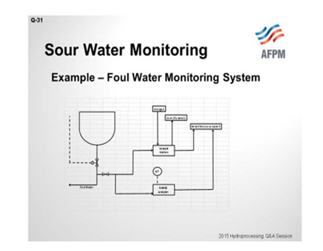
And then on this last slide, I have drawn a fairly simplified schematic of several of our units where we have a closed-loop sampling system off of the foul water system at the bottom of the vessel. Also incorporated around that sample station, which is done with some amount of frequency, is an analyzer loop that will also be a continuous tie-in to our DCS (distributed control system).
EPSTEIN [Flint Hills Resources, LP (FHR)]
At Flint Hills Resources Pine Bend Refinery, the high pressure side NH4HS concentration in the sour water is calculated according to API 932B assuming that all organic nitrogen removed (from mass balance between feed and product nitrogen) forms NH4HS with the excess H2S available and is washed to the high pressure sour water boot. Feed and product nitrogen analysis is key in this calculation. Use of the calculation is conservative for NH4HS concentration and eliminates the need for frequent water sampling. In addition, sample stations that are designed with restriction orifices, valves, and flow-through design around the high pressure letdown valves are used. A septum lid on the glass bottle allows flow sampling of the lower pressure liquid. This water is tested for chlorides, pH, iron, NH3, and H2S which are used for verification of adequate separation and waterwash mixing.
Samples are taken of the sour water on the hydroprocessing unit’s low-pressure side (cold low-pressure separator boot and fractionator overhead accumulator) for ammonia, sulfur, pH, chlorides, and iron testing. These samples are taken in bottles and tested at the site laboratory using Standard Method 4500-NH3 D for NH3. The laboratory system of labelling for these samples includes warning of the presence of H2S and NH3 for safety in handling.
MORELAND (Valero Energy Corporation)
First of all, I agree with what Scott and Paul said about safe practices for sour water monitoring. At Valero, we also require fresh-air and closed-loop sampling for those hazardous samples. Our standard is to compare the feed-based nitrogen calculation for ammonia bisulfide, which is outlined in the API 932B, based on pounds of nitrogen removed. We compare that ammonium bisulfide result to the lab sample result based on ammonia and H2S. The calculation and lab results tend to agree within about 10%. If they do not, then that gives us a good indication that we need to go look at the sampling method. Potentially, we could be losing some H2S from those samples. We also check sour water pH, iron, and chloride content, like Paul mentioned. We have a system in place at Valero to flag these sample results if they are above a predefined limit. Those flags are communicated up not only to the refinery leadership team, but also to our corporate refinery management as well.
ALMA SCHURIG(Big West Oil, LLC)
We had a one-off situation where there was hard water leaking into our sour water system from a cold water exchanger (in the crude overhead cooling system). Since then, we have also started monitoring for hardness in our sour water feed. The hard water quickly caused us problems in our sour water stripper. It plugged the stripper with hard water deposits and shut down the unit. So I am curious if anyone has had enough problems with hard water ingress that they have implemented regular hardness monitoring of the sour water.
MORELAND (Valero Energy Corporation) I do not know if we have had an issue with the hardness, but we do have hardness specifications for the water we use for waterwashing our hydrotreating units which have been specifically placed for those issues. I am not aware of Valero has experienced the issue.
McARTHUR (Phillips 66) Likewise here. We do have hardness specifications for washwater supply, but I do not think we typically test the foul water.
Year
2015
Process