Lauren Grimm
US Chemical Safety Board
Kaspar Vogt (Albemarle)
In some processes, hydrotreating catalysts are used to treat feedstocks containing very low sulfur (below 20 ppm). These processes can include the following:
1. Gulf HPG process for treating pyrolysis naphtha (second stage).
2. Two step naphtha hydrotreating process in steam reforming (ammonia synthesis process).
3. Treating olefinic fuel gas prior to reforming to make synthesis gas for methanol manufacturing.
4. Wax and certain lube hydrofining operations
It appears that in these processes the catalyst slowly loses its HDS activity. This is due to the transformation of the Molybdenum present as activator, and Nickel/Cobalt present as promoters, from their active sulfide form to the inactive metal state. This process is caused by a hydrogen sulfide partial pressure that is too low (see phase diagrams below).
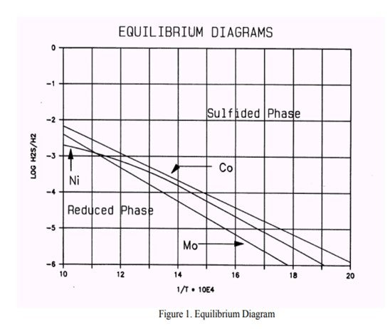
In some cases (usually naphtha units) conditions can arise that contribute to a low H2S partial pressure and could result in metal reduction. Based on the feed properties, operating conditions and product objectives, we can determine whether the unit is or will be operating in a critical operating window. If this is the case, a spiking agent such as DMDS should be added to the feed to boost the H2S partial pressure.
From the phase diagram shown above, we see that the Cobalt is the most critical element. We can begin to move into the Co8S9-phase by decreasing the temperature or increasing the H2S partial pressure by adding sulfur. To move into the "safe" region of the diagram, the Log10 H2S/H2 should be at least -4 at a temperature of 640 deg F.
If the same calculation is done in the reverse order the minimum feed sulfur to avoid metal reduction can be calculated. If we process a 1 ppm sulfur, 70°API naphtha feed at 360 psig at 640 deg F, 80% H2 purity, down to 0.4 ppm sulfur in the product (actual sulfur removal is 0.6 ppm) we conclude that 20 ppm sulfur should be added to avoid catalyst metal reduction. Spiking can be done with a sulfiding agent, e.g., DMDS, DMS.
Minh Dimas (CITGO)
For diesel hydrotreaters, as long as the material being fed to the reactor contains sulfur (i.e., sour feed) and the recycle gas contains 25-50 ppm H2S (by adjusting the amine circulation when necessary), there should not be a need to inject a sulfur-spiking agent into the feed. This ensures a small concentration of H2S at the inlet of the reactor. With reactor temperatures above catalyst activation temperatures, additional H2S is being generated from that point on through the reactor. For us, the sweetest feed is observed when reprocessing off-spec diesel, in which case we may shut down the Recycle H2 Amine Scrubber to preserve the H2S and protect the catalyst.
Tim Lewer (Shell)
In hydrotreating units where the feed sulfur is low and the temperature and H2 partial pressure are low, operation with as low as 20 ppm H2S in the recycle gas has been observed. There is not, however, a universal minimum concentration requirement. The minimum required H2S concentration will vary from unit to unit depending on many factors including, but not limited to: unit feed sulfur concentration, unit pressure, reactor temperature, catalyst type, vent rate, catalyst age, and H2 partial pressure. It is common practice to inject a sulfiding agent such as DMDS to maintain adequate H2S in the recycle gas. In addition, refiners have used sour make up gas streams to provide adequate H2S partial pressure. The guidelines can change based on what catalyst company you talk with, but it all depends on how conservative you want to be. You need to set the H2S low limit to provide a proper buffer zone. It is recommended to discuss H2S concentration requirements for all situations with your catalyst vendor to make sure the catalyst is properly protected against metal reduction.
Gordon Chu (ART)
There is no minimum hydrogen sulfide requirement as long as the feed contains some sulfur as the sulfided catalyst is very resistant to sulfur loss under normal process conditions. We are not aware of any refiners adding sulfur compounds to maintain a minimum H2S concentration during the process cycle.
Tim Lewer (Shell)
On freshly activated catalysts, the surface is relatively clean (free of coke) and therefore is unusually active. This is sometimes referred to as hyperactivity. In order to maximize catalyst stability for good cycle length, it is important that the rate of coke lay down on freshly sulfided catalyst is gradually controlled. Upon completion of metals sulfiding, catalyst hyperactivity exists, but is short lived as feed processing lays initial coke on catalyst. Processing cracked stocks that contain more reactive molecules and coke precursors too early over the hyperactive catalyst can result in operability issues through cracking while accelerating the initial coke lay down on catalyst.
Cracked stocks contain large amounts of aromatics and olefins, which release large amounts of heat when saturated. Aromatics and olefins undergo saturation, but they can also condense or polymerize to form larger molecules, gums, and coke. When cracked stocks are introduced too soon, passing such highly reactive molecules over hyperactive catalysts leads to excessively high reaction rates. The resulting high exotherms aggravate the situation, because reactions like polymerization are faster at higher temperatures. By processing only straight run feeds for the first 72 hours after catalyst activation, the initial coke lay down is gradual for improved long-term stability.
The cracked stock introduction rate varies by unit, but should allow for exotherm stabilization, reestablishment of unit pressure as H2 consumption increases, and coordinated with smaller temperature additions to treat the more reactive feed molecules.
Minh Dimas (CITGO)
I understand “break-in” to be the same as “catalyst conditioning period” – i.e., three days of straight run material only (no cracked stock). It is imperative to adhere to the three full days of break-in (or catalyst conditioning) period following the catalyst activation/sulfiding (which is not included in the three days). After the catalyst is successfully conditioned, the cracked feed can be introduced as quickly as desired by Engineering and Operations (comfort factor) and as manageable by the unit equipment and utilities (i.e., charge heater, hydrogen makeup rate vs. consumption, reactor quench ability, etc.). Since the catalyst conditioning period “quenched” the hyper-active sites of the catalyst, the introduction rate of cracked material after the catalyst break-in / conditioning is negligible.
Kaspar Vogt (Albemarle)
Cracked and heavy feedstocks contain significant quantities of hydrogen deficient molecules known as “coke precursors”. These coke precursors (olefins, poly-nuclear aromatics, asphaltenes, concarbon) tend to polymerize, condense or form coke, given the right set of reaction conditions. Freshly sulfided catalyst, with little or no carbon deposits, is in an ultra-active state. Coke precursors in the feed readily react on the catalyst to produce a molecule with an extremely reactive free radical site. Ideally, this site would react with hydrogen but, because there are so many reactions taking place on the catalyst in its ultra-active state, there can be localized hydrogen deficiency. Without hydrogen readily available to react with the free radical site, the molecule may polymerize or condense with another active molecule, or it may simply deposit on the catalyst surface as coke. All of these outcomes result in blocked pores and/or active sites. Fresh catalyst has hyperactivity due to the absence of coke. Once coke has laid down, the catalyst reaches its design activity, and the coke prevents the agglomeration of metals.
Testing shows the loss of activity between immediate and a three-day waiting period before cracked feed introduction to be 10-15%. We recommend to stepwise increase the amount of cracked stock, which will have a higher exotherm, so that the unit does not incur large temperature swings. It varies per unit depending on the feeds and operating conditions but typically addition of 10% of cracked stocks per two-hour period is good operating practice.
There are commercial offerings available to ex-situ sulfide the catalyst with a special cracked feed protection (CFP) treatment for direct introduction of the cracked feed.
Ben Sim (ART)
Introducing cracked stocks too early after sulfiding will cause noticeable loss in activity. Coke precursor molecules in cracked feeds will have a tendency to form coke over the fresh and highly active sites on the catalyst. By delaying the introduction of cracked stocks for at least 3 days after sulfiding will allow the catalyst activity to be passivated which helps to minimize these effects.
After running for three days on straight run the cracked material should be added to the feed stream gradually. ART typically recommends adding the cracked feed in small increments every shift making sure the reactor exotherm remains under control and within acceptable limits before increasing the cracked feed amount any further.
Martin Gonzalez (BP)
We have used a terpene-based product to help free hydrotreater reactor circuits of hydrocarbon in preparation for catalyst change-out. The product was effective for achieving a low level of combustibles in the reactor and in all vessels of the reactor circuit. However, in one instance, the test for entry indicated high benzene levels, and further nitrogen purging was required. As a result, the benefit of a quicker shut-down was not fully realized. In our trials, the greatest gains in shut-down duration resulted from the review and optimization of cool-down procedure that took place in preparation for the injection, rather than from injection of the chemical itself. Also, note that chemical may heat up the catalyst upon application, due to a relatively high heat of adsorption. Such a warmup may extend cool-down time beyond what was anticipated.
Tim Lewer (Shell)
Some plants have used additives during the hydrotreater reactor cool down period in order to remove hydrocarbon, especially benzene. These additives have been used with varied degrees of success. To this date, data has been inconclusive as to whether or not the chemical additive speeds up reactor decontamination versus conducting a proper hot hydrogen strip.
Injection of chemical additive requires several extra considerations in addition to the expense of the chemical:
• Waste disposal – Chemical suppliers may claim that their product is safe for refinery re-run systems, but most plants will be hesitant to re-run through the crude unit due to concerns, for example crude column overhead corrosion.
• Piping for injection – Temporary piping needs to be installed in order to inject chemical to the desired locations. This creates additional expense and maintenance workload during unit shutdown. Also, many plants may not allow connection to the process until the unit is down to a low enough pressure.
• Hold points – Many chemical additives need hold times at certain temperatures per the manufacturer to guarantee hydrocarbon removal. This will add time to your cool down.
Kaspar Vogt (Albemarle)
We have experience with dumping, screening and reloading hydrotreating and hydrocracking catalyst. Here are two typical times this occurs:
1. After a full cycle – In these cases spent catalyst has been reused, without regeneration or reactivation, in a lower severity application for which the remaining activity is sufficient.
2. Early in the cycle – If at the start of the cycle the pressure drop is very high (due to, for example, broken inert balls or when significant maldistribution in the catalyst bed is measured), it can make sense to unload, screen and reload the catalyst.
Although it has been performed successfully, more often it has led to more pressure drop problems.
Best practices:
First, the safety aspects of handling a pyrophoric or self-heating material MUST be addressed. We believe it is critical to use proper detectors (SOX, H2S, etc.) and have proper emergency procedures and properly trained personnel in place before executing the catalyst dumping, screening and reloading process.
It is also important to dry the catalyst before unloading. Dust and small particles stick to the oily catalyst during dumping and screening and are not removed until liquid washing of the catalyst surface. This can lead to fouling of the catalyst bed and reactor internal trays and create excessive pressure drop at restart. H2 stripping to remove liquid between particles before unloading the catalyst is highly recommended.
It is important to split the different catalysts layers by either vacuum unloading guard and grading layers from the top or size screening after dumping in order to be able to reload a properly designed catalyst system.
If the screening is done on-site, we recommend the use of a relatively large screen to ensure broken fragments and small particles are rejected. This will prevent differential pressure issues with the reloaded material.
Providers of onsite screening services are typically limited in available equipment compared to offsite specialized companies. It is important to have adequate equipment to determine the particle size distribution of the screened catalyst. Evaluating the entire length distribution and not just the average length is a critical step for preventing excess pressure drop. It is also advisable to conduct a pressure drop test on the pilot scale to fully evaluate the effectiveness of the screening and predict the corresponding pressure drop for the screened catalyst load. Often some additional fresh guard, grading and main bed catalyst is needed to ensure a complete reactor fill.
Martin Gonzalez (BP)
Dump, screen, and re-load of spent hydrotreating catalyst are usually unattractive for various reasons. To minimize oxygen exposure, catalyst loading companies can usually keep screening equipment under inert atmosphere. Vacuuming catalyst rather than dumping can help to simplify screening by avoiding a mix of many sizes of material. Modern vacuuming equipment can also result in less breakage of catalyst, compared to gravity unloading.
Tim Lewer (Shell)
The practice of unloading, screening, and reloading still-viable hydrotreating or hydrocracking catalysts during turnarounds and without off-site regeneration has been done successfully – with catalyst vendor on-site support or project management. However, there are numerous factors involved in the decision to do so, especially with the advent of stacked bed catalyst schemes with multiple layers of materials either equal in size or too close in size to screen successfully using typical mobile equipment. For single bed hydrotreating reactors, which often contain a majority of same type/size catalysts, the task is more manageable but still a complex undertaking.
Extensive pre-planning is paramount to the success of this type of operation. There are a number of “best practices” that will help to ensure a successful outcome after the decision is made to re-load unregenerated catalysts versus loading fresh catalysts:
1) Research and hire a catalyst handling contractor that possesses the latest catalyst vacuuming/N2 recirculation, dust control, and screening equipment. All equipment used in such an endeavor must have the capability of being effectively purged with nitrogen.
2) Vacuuming support/grading layers from the tops and bottoms of beds and keeping these materials separate from main bed catalysts will allow for quicker screening rates and cause fewer losses due to breakage.
3) Ensure that there are excellent QA/QC measures in place, such as container labeling (where in the bed material is from, pre- and post-screened tare and net weights of all containers, etc.) and strict, written tracking and segregation of unscreened and screened containers.
4) It is imperative to establish clear guidelines prior to the start of the project to ascertain what properties need to be met in order for screened catalysts to be acceptable for reloading. These guidelines should include acceptable levels of fines, average catalyst length, and acceptable levels of cross contamination between different catalyst types and/or sizes. Screen sizes and opening shapes (slotted or square), controlled rates and constant oversight by personnel aware of the established guidelines and desired outcomes of the screening operation are critical to a successful end product.
5) Consult with your catalyst supplier to arrange for lab testing of unloaded materials to ascertain viability of the catalyst and be prepared to perform average length testing on-site (pre and post screening) to ensure catalyst to be reloaded will meet preset guidelines and properties and perform as desired. Catalyst and support losses due to breakage and attrition must be anticipated with assurance that ample make-up quantities of all materials are in ready supply and available as needed. It is also wise to have a “Plan B” prepared in the event that results are less than desired.
6) Pre-plan for sufficient acreage to accommodate a high traffic operation with requirements for staging of empty, unloaded (full) containers, weighing (pre- and post-screening), and staging of materials for reloading. Screening areas should also have weather protection constructed prior to the start of screening operations.
Greg Rosinski (ART)
Spent hydroprocessing catalyst is pyrophoric due to small particulates of iron sulfide scale that are present, so care must be taken to minimize the exposure of the spent catalyst to air. In addition, spent sulfided catalyst has some coke on it and it will slowly oxidize in air. If the spent catalyst is exposed to air, it will slowly heat up, and if iron sulfide is present, it will combust which may ignite the coke or other residual hydrocarbon on the catalyst.
The key to this procedure is to have competent and experienced personnel performing the required tasks. The reactor must be thoroughly swept of hydrocarbons, and a nitrogen purge should be kept on the reactor at all times. During the unloading, the screener and the dump nozzle should be continuously purged. The containers that will hold the catalyst during unloading should be blanketed with nitrogen or have dry ice placed inside until ready for loading. The containers should not be open to the atmosphere. The loading should be done under inert conditions with experienced personnel.
When preparing your procedure, make sure to involve your refinery EH&S group and give careful consideration to all aspects or the process to ensure you take all the precautions necessary.
Kaspar Vogt (Albemarle)
Refiners make two types of product kerosene:
- Jet A-1 has a total maximum sulfur specification of 3000 ppm and a mercaptan sulfur concentration of no more than 30 wppm.
- Ultra low sulfur kerosene (ULSK): has a total sulfur concentration of less than 10 ppm
Sweetening processes, such as caustic treating or UOP Merox™, selectively remove mercaptans without otherwise affecting the kerosene composition. Hydrotreating, by contrast, affects several key properties of the kerosene including smoke point, aromatic, sulfur, and nitrogen content and other properties such as oxidation stability. This becomes important as ULSK becomes more prevalent in the market. As a result, kerosene sweetening can typically easily achieve the Jet A-1 specifications. Hydrotreating is typically required for nearly complete removal of kerosene sulfur.
Kerosene Merox™ Sweetening is not an extraction but conversion process that requires a catalyst and oxygen to convert mercaptans to disulfides. It takes mercaptan sulfur species and oxidizes them to form disulfide. The disulfides remain in the product but do not impact the corrosion properties to the same degree as mercaptans. The conversion of mercaptan to a less objectionable sulfur form, disulfide, will help meet final specs for the kerosene fraction. Merox™ Sweetening can typically achieve the Jet A-1 specifications. However, it is difficult to guarantee thermal stability due to the presence of mercaptan sulfur species.
Caustic extraction alone generally results in very low yields of extracted sulfur. The mercaptan sulfur species are just too difficult to extract via aqueous alkanolamine (e.g., caustic) solution. There may be very few cases where employing mercaptan extraction plus sweetening is feasible. For this application to occur the crude is likely to have a low amount of sulfur and the kerosene fraction is relatively light. This allows for a larger fraction of lighter mercaptan sulfur species which may be partially extracted.
In a few cases some aromatics saturation is required to achieve the smoke point and naphthalene’s specification. For these cases, hydrotreating is needed.
In ULSK hydrotreating, color issues can occur and are typically related to insufficient treat gas and hydrogen partial pressure
For hydrocracker kerosene, a caustic wash should be added if the product needs to meet Silver Strip Corrosion. However, if the product just needs to meet copper (Cu) Strip, then caustic wash is typically not needed.
Another factor that should be considered is the capital required for a hydrotreater versus a Merox™ unit.
Martin Gonzalez (BP)
The most obvious difference between sweetening and hydrotreating is that hydrotreating will reduce total sulfur, while sweetening processes simply convert mercaptan sulfur into disulfides without removing sulfur from oil. For production of jet fuel, the total sulfur in the kerosene is a key consideration. We have found that a shift to a sourer crude diet such as Canadian Extra Heavy Oils may precipitate the need for hydrotreating. Depending on the pressure of the hydrotreater, it may also be possible to improve the smoke point or aromatics content of the feed, where sweetening will not. Hydrotreating will also remove the surfactants responsible for water separation problems (WISM), thus eliminating the need for clay treating. In addition, thermal stability (JFTOT) of the fuel should be much improved by hydrotreating.
Dave Krenzke (ART)
The decision to use hydrotreating or a sweetening process depends on the types of sulfur in the kerosene and the product sulfur target. Hydrotreating can remove all types of sulfur compounds and therefore the sulfur content of the product is only limited by the process conditions and catalyst activity. The sweetening process only removes mercaptan sulfur, so the product sulfur is limited to the non-mercaptan sulfur in the feed.
Kaspar Vogt (Albemarle)
The purpose of adding more LCO is to improve the refinery’s financial performance by upgrading low value LCO to ULSD products.
The optimal 95% distillation point depends on operating conditions (H2 partial pressure and space velocity), unit objectives (cycle length / uplift) and product specifications. Adding heavier LCO can be limited by the specifications set on minimum cetane number/index, diesel density, PNA concentration and distillation. Adding heavier LCO will also introduce more sterically hindered dibenzothiophenes (very difficult sulfur species) and additional nitrogen compounds (inhibitors for HDS reactions) and 3-ring aromatics in the feed.
Using high activity catalysts such as STARSTM and NEBULA® can allow refiners to process heavier LCO, provided enough hydrogen is available. These catalysts have high hydrogenation activity to convert sterically hindered sulfur, uplift density and improve Cetane.
The availability of sufficient hydrogen is critical. Processing more LCO will require additional operating temperature and increase the exotherm in the catalyst beds due to the presence of more polyaromatics. Furthermore, the additional hydrogenation reactions will cause a corresponding increase in hydrogen consumption. This will reduce the operating window, increase the deactivation rate and set a shorter cycle length. If the cycle becomes uneconomic due to down time and turn around costs it can limit the operating strategy of processing more and heavier LCO.
In cooperation with a US refinery, a commercial test was run where the LCO 95% and End Point (EP) were increased when the turnaround had been set and sufficient catalyst activity remained which the refinery chose to use up. The unit has a 1000 psig inlet pressure. The results of the test gave an interesting plot of required weight average bed temperature (WABT) vs. on stream time as the LCO became increasingly heavier.
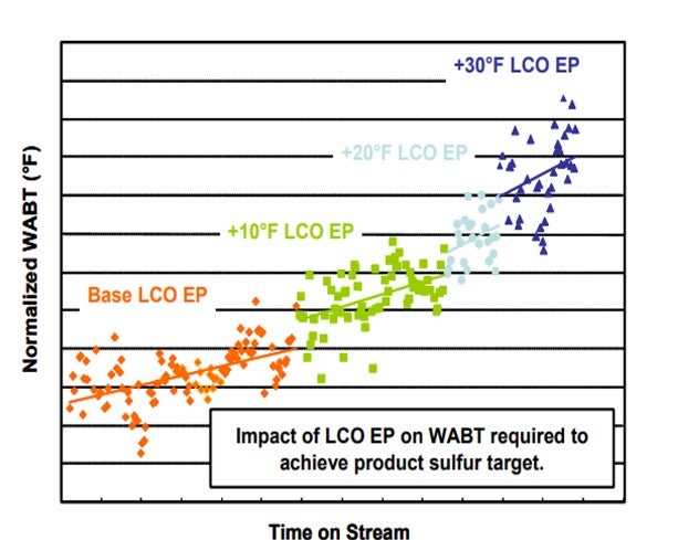
In the figure above, we can clearly see that processing higher end point LCO requires additional operating temperature and increases the deactivation rate. We also see that end point increases of as little as 10 deg F can significantly increase both the required WABT, and the deactivation rate.
Martin Gonzalez (BP)
Difficulty in desulfurizing LCO relates directly to the concentration of hindered substituted dibenzothiophenes (DBT's). The optimal cut-point may be different for each hydrotreater depending on the individual capabilities of that unit (pressure, space velocity, and duty limits). Concentration of DBT's will also vary depending on degree of hydrotreating of FCC feed, and LCO total sulfur concentration may not be a good indicator. Our experience is that coke lay-down rates on catalyst will be greater as the concentration of polyaromatics increases. Thus, it becomes important to also consider LCO gravity, in addition to final boiling point and normal boiling point when considering deactivation rates.
Minh Dimas (CITGO)
We typically target LCO final boiling point instead of 95%. This is because with a constant 95% distillation point, the FBP can vary significantly – at least that is our experience. As the boiling point of LCO material increases, the difficulty to hydrotreat (as opposed to hydrocrack) grows exponentially. Because of this, there is an inherent hydrotreating catalyst life penalty with increased LCO distillation FBP. Of course, the degree of the penalty depends highly on a number of variables including but not limited to the total volume of catalyst, reactor temperature control / quench control, feed nitrogen concentration, feed sulfur concentration, and catalyst type. The unit design (system pressure, hydrogen purity, etc.) has a smaller effect.
Brian Watkins (ART)
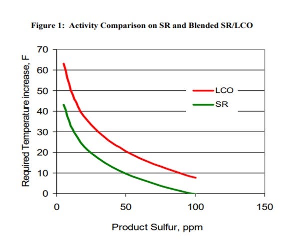
The addition of LCO to a ULSD hydrotreater has several effects such as increased hydrogen consumption, higher required reactor temperatures and possibly shorter cycle time. Figure 1 summarizes some of pilot plant data comparing a SR and a SR/LCO feed blend. It shows that the SR diesel requires a 43°F increase in temperature to go from 100 ppm sulfur down to 10 ppm sulfur. The 20% LCO blend requires almost 20°F higher temperature to achieve the same product sulfur relative to the SR feed. The product from the LCO blend also has a 2 to 3 number lower API compared to the SR product, and hydrogen consumption increases significantly for the LCO blend due to saturation of additional polyaromatic compounds found in the LCO. These latter consequences set limits on the amount of LCO which can be processed and still meet product cetane specifications and also hydrogen availability constraints.
One option to re-gain some of the lost activity in adding additional LCO is to change the end point of the LCO in the feed. ART completed pilot plant testing on an LCO from the same FCC which had been cut at two different end points. Table 1 lists the analysis of the two LCO feeds and shows that the end points differed by about 40° F. The decrease in endpoint lowers the total sulfur by almost 1000 ppm and total nitrogen decreases by 129 ppm.
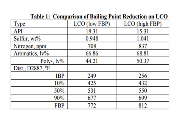
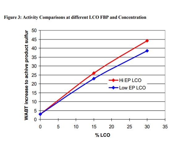
A comparison of activity on the two LCO feeds blended at 30% by volume into SR feed is shown in Figure 2. Over 30° F higher temperature is required to treat the higher endpoint feed to ULSD specification. This difference in activity corresponds to a significant decrease in the hydrotreater cycle length.
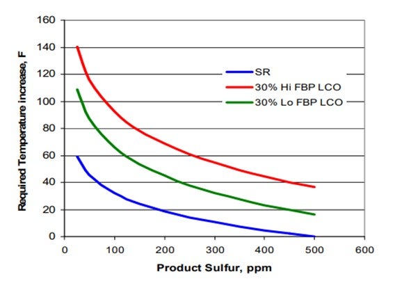
The addition of LCO has a major impact on activity for both the low and high endpoint LCO materials. The required temperature increase for ULSD in going from 0 to 30% LCO for the lower endpoint material is about 1.2° F per percent LCO. Processing the higher endpoint LCO increases the required temperature to about 1.4° F per percent LCO. Figure 3 demonstrates this more clearly in the form of a plot of the required temperature increase as a function of LCO content. Notice from the chart that the activity effects are not exactly linear with increasing LCO content. The first 15% LCO has a larger impact on activity than the next 15%.
Raj Patel (Haldor Topsoe, Inc.)
In the current market, a strong driver for many refiners to increase profitability is to increase the production of diesel; this can be done by increasing the end point of the LCO to the diesel hydrotreater to make more high value ULSD as compared to low value slurry oil.
It is clear that the higher the LCO cut point, the larger the ULSD product pool value. However, a great number of other considerations need to be addressed when increasing LCO cut point to the diesel hydrotreater with the primary concern being reduced catalyst cycle length.
Ideally there would be a single LCO 95% distillation point that all hydrotreating units should target to optimize the ULSD production, i.e., optimize the economics of the diesel hydrotreater. There is, however, no single LCO 95% distillation point that can be considered optimum for all hydrotreaters. Diesel hydrotreaters are designed for processing different feeds and different processing objectives. This results in units with different hydrogen partial pressures and LHSV. The limiting processing objective could be meeting ULSD sulfur, cetane number, cold flow properties, color product end point etc. All these constraints need to be considered individually, and it needs to be determined which will be the limiting constraint not only at SOR but also at EOR. Increasing LCO end point could possibly decrease attainable EOR temperature before the ULSD product goes off spec, effectively shortening the catalyst cycle length. Therefore, there is no single LCO 95% distillation point that can be considered optimum for all hydrotreaters. The ASTM D-86 distillation may hide a lot of the heavy end species, so it is recommended to use ASTM D-2887 distillation when looking at 95% boiling point.
Common for all hydrotreaters is, however, that hydrotreater catalyst life will be penalized with increased cut points. The reduction in catalyst life will come from increase in the required SOR WABT, increased deactivation rates and possibly reduced EOR temperatures:
Activity – Required SOR WABT
As a general rule of thumb for treating 100% LCO, it can be assumed that for every 2-4°F increase in LCO 95% boiling point, the required Weight Average Bed Temperature (WABT) of a hydrotreater must be increased by approximately 1°F to compensate for the increased feed sulfur and feed nitrogen levels. However, this impact is very pressure dependent. If the portion of LCO is smaller, it can be assumed that the required increase in WABT will be almost proportionally less.
If the cut point is lowered towards the end of the cycle, then the increase in required WABT will be regained due to lower severity feed (less sulfur, in particular the difficult sulfur species, and less nitrogen, which inhibits the hydrotreating reactions). If reducing end point for winter month operation, where cold flow properties are limiting, then the hydrotreater can be operated through the winter months with the lighter feed, even if the catalyst is at EOR in summer mode. However, the catalyst life lost from increased deactivation rate when processing the higher end point LCO will not be regained.
Catalyst deactivation
The other effect to consider when raising LCO end point is catalyst deactivation rate. This effect will be dependent on the increase in Tri+ aromatics and nitrogen content of the LCO. As a general rule of thumb the deactivation rate may increase by up to 10% for every 10°F increase in LCO EP. Based on the above it is clear that increasing LCO cut point will negatively impact catalyst life from a standpoint of catalyst activity as well as stability. Increasing LCO cut point (or other heavy portions of the feed in general) must ALSO be managed to meet properties other than sulfur, including cold flow properties, color, cetane number, distillation spec and gravity. Several of these specifications may lead to a lower attainable temperature at EOR due to equilibrium constraints.
The use of the various feed stocks available to the refiner (including LCO) to a diesel hydrotreater is ideally optimized through not only the use of proven kinetic models but also must include refinery LP models. This will provide detailed predictions on the costs and benefits of increasing the cut point of the available feed stocks.
Topsoe has designed diesel hydrotreaters processing LCO including multiple units processing 100% LCO.
Minh Dimas (CITGO)
Volume gain requires hydrogen consumption. Aromatic saturation reactions consume the most hydrogen, followed by olefin saturation. For same feed qualities and same LHSV, the units that make higher cetane product will have higher volume gain due to more aromatic saturation. The main factors for maximum unit volume gain include degree of aromatic saturation, reactor temperature, catalyst type, feed characteristics (aromatic and olefinic content), and space velocity (lower space velocity favors volume gain). However, we do not have data to correlate space velocity and volume gain, specifically.
In general, volume gain for feed components can be listed in decreasing order as follows: Light Cycle Oil, Coker Light Gas Oil, Coker Kerosene, Crude Diesel, Crude Kerosene, and Coker Naphtha. The volume gain to be expected for each feed component is highly dependent on the aromatic and olefinic content (and therefore hydrogen consumption) of those components, so it is difficult to give specific volume gain expectations. It is best to use relative volume gains between specific feed components based on each component’s hydrogen consumption and/or aromatic content.
Note that aromatic saturation is reversible at higher reactor temperature. Therefore, for units that process very sour feed, a higher reactor temp will be required to meet the sulfur spec of the diesel product. However, higher temperature may lower the aromatic saturation, and thus, lower the volume gain.
Kaspar Vogt (Albemarle)
Absent from some form of cracking, the volume gain possible is mainly determined by the concentration of aromatics in the feed. At a given set of conditions (feed, pressure and feed rate/space velocity) the aromatic saturation will be determined by the catalyst activity. The desired reactions are the saturation of poly and mono aromatics which are enhanced with NiMo or NiW catalyst at medium and higher pressure vs. CoMo catalyst. Stacked systems of catalyst can optimize the H2 consumption versus the performance objectives.
Lowering the feed rate will increase the residence time, which is favorable for increased aromatic saturation. However, mono aromatic saturation occurs slowly at typical hydrotreater conditions so density uplift may not be high if polyaromatics are absent from the feed. For individual feed components, the volume gain comes from aromatics saturation and heteroatom removal. The density of paraffins and naphthalene's are not affected significantly in the hydrotreater.
Most ULSD hydrotreaters have a start of run operating temperature in the kinetic regime of the operating window and will hydrogenate aromatics. Once the unit operates past its maximum saturation temperature, in the thermodynamically controlled regime, net aromatics saturation decreases and volume gain will begin to decrease as well. Continuing to increase the operating temperature will further reduce the volume swell. Operating at the maximum saturation temperature is an operating strategy known as max arosat and maximizes the volume swell as well as Cetane uplift for a ULSD unit.
Shankar Vaidyanathan (Flour)
The volume gain in higher pressure ULSD units handling cracked stocks as a portion of the feed blend is often set by the hydrogen consumption for ring opening and aromatic saturation. A rule-of-thumb is that, approximately 25-30 SCFB chemical hydrogen is consumed for every 1% of aromatics saturation, and the resulting gravity improvement gives 0.1 LV% synthetic volume gain. Assuming HDS objectives are met, the optimum point should be the combination of aromatic saturation, cetane and gravity targets without giving away product specifications in the blended pool. Since hydrogen is neither cheap nor available in unlimited quantity, the catalyst system is often tailored in the ULSD units to minimize hydrogen consumption while just meeting production objectives.
Aromatic saturation is an equilibrium limited reversible reaction for a given unit hydrogen partial pressure and a specific catalyst system. Lowering the space velocity will lower the temperature to promote aromatic saturation. In new designs, aromatic saturation through the catalyst cycle is considered while selecting the catalyst system, setting the pressure and configuring the reactor. Some diesel hydrotreaters have a separate aromatic saturation reactor that operates colder with noble metal catalyst and these designs have incremental cetane boost and volume gain. Lowering space velocity in an operating ULSD unit is impractical since reducing the feed rate negates the volume gain benefit.
Charles Olsen (ART)
There are a number of parameters which influence volume gain in a ULSD unit. Hydrogen partial pressure and LHSV are two key operating conditions which have a large effect on the product volume increase. Catalyst selection also plays an important role since at higher pressures NiMo catalysts have a higher aromatics saturation activity compared to CoMo catalysts.
Figure 1 shows the total volume yield on a fresh feed basis that has been achieved in several commercial diesel hydrotreaters as a function of unit LHSV. Generally speaking, as LHSV decreases the potential volume swell increases. At a LHSV around 1 hr-1 or less, total product volume increases of 6-7% or more are achievable (provided the H2 pressure is high enough), while at a LHSV greater than about 1.7 hr of the total product volume increase is about 1-2%.

Of course LHSV is not the only parameter which can influence the volume swell. H2 partial pressure also has a significant effect. Figure 2 summarizes the total product volume yield as a function of unit pressure for the commercial units shown in Figure 1. Not surprisingly, higher pressure units tend to achieve much higher level of volume swell. In these examples, the volume increase is typically less than 3% when the unit pressure is less than 1000 Psig. The total volume swell increases to the 4-7% range as pressure increases beyond 1000 Psig. The data in figures 1 and 2 also suggest there is a practical limit to the volume swell achieved from typical hydrotreating. A Comparison of the volume swell achieved by Refiners A and B shows they are roughly the same for both units despite the large difference in operating pressure at similar LHSV.

The volume swell also varies significantly with feedstock. Figure 3 summarizes how the total product volume yield correlates with the API gravity of the feed. In general, the product volume swell increases as the feed API decreases. In other words, as more FCC LCO is added to the feed the potential volume swell from hydrotreating increases. As mentioned previously, the catalyst will also have an impact on the degree of volume swell achieved in a hydrotreater. It is well known that NiMo catalysts have higher aromatic saturation activity than CoMo catalysts, and therefore a NiMo catalyst is expected to deliver greater volume swell. Figure 4 summarizes pilot plant data which demonstrates this. These data were generated using a 25% LCO containing feed and shows that the NiMo catalyst results in 1-2 numbers higher total product volume increase compared to the CoMo catalyst.

Raj Patel (Haldor Topsoe, Inc.)
In ULSD units, volume gain is achieved through HDS, aromatics saturation, and hydrocracking if converting diesel into naphtha is desirable. The type of feedstock and operating conditions such as pressure and catalyst volume will set the amount of volume swell. Lowering the space velocity will increase the aromatics saturation if the operating temperature is in the kinetic-controlled regime. There is a significant difference in volume swell for different type of compounds, and the volume swell is therefore very dependent on the feedstock. Obviously, the feed that has the most sulfur, olefins and/or aromatics will give you the highest volume swell since it will consume the most hydrogen. If the refiners are trying to maximize volume swell, then they should operate their existing hydrotreating unit at the highest hydrogen partial pressure possible and utilize catalyst that has a high hydrogenation function. Topsoe’s NiMo BRIMTM catalyst are specifically designed to utilize the Brim catalyst sites as well as the Type II site for maximizing HDS, HDN and HDA activity resulting in a high-volume swell. For a grassroots design, consideration should be given to a two-stage design with aromatic saturation catalyst in the second stage to maximize volume swell.
Kaspar Vogt (Albemarle)
Due to the increasing global demand for diesel, the ability to reduce product density (increase volume gain) and blend a significant amount of heavy diesel and/or light vacuum gasoil in the ultra-low sulfur diesel pool represents a large economic advantage. These economic gains could potentially include margin increases of tens of millions of dollars per year for a refinery.
Typical mild hydrocracking units operate between 800 and 1200 psig with a conversion level of around 30%. The cracking catalysts selected in lower pressure units are amorphous silica alumina catalysts. Zeolitic catalysts are applied in higher pressure operations. We have extensive experience in mild hydrocracker (MHC) operations including maximizing USLD production and/or maximizing density reduction.
Normal hydrotreaters are not designed for hydrocracking and below we list the issues to address when converting the ULSD unit to a mild hydrocracking unit. First and foremost, the safety of the employees, community, and equipment needs to be considered. The risk of a temperature run away is very limited in hydrotreaters, while in hydrocracking it can happen if the proper precautions and counter measures are not in place. The measures include:
- Proper emergency shut-down procedures
- Operator training
- Good liquid and gas distribution
- Well-designed quenches
- Proper unit control with advanced control systems
It is important to be conscious of the typically large lag time in the unit and the fact that relatively small changes of the process parameters can result in considerable cracking bed responses.
Also important in the evaluation is the presence of or access to sufficient hydrogen to the unit and a thorough review of the fractionation section. The increased conversion will lead to increased light end yields. The unit separation equipment must be able to accommodate these higher yields in the reactor effluent.
By adding hydrocracking catalysts in the existing unit, a catalyst system needs to be designed to offset the activity loss of the hydtrotreating catalysts that are displaced. Such measures include the usage of higher activity pre-treatment catalysts similar to those used in hydrocracking.
The hydrogen partial pressure does not need to be very high. For example, a commercial unit processing diesel with LVGO at a total reactor inlet pressure of 750 psig accomplished 50% 660 deg F conversion and 9.5 deg API density reduction. In this example, the hydrogen consumption roughly doubled.
In general, higher pressure will promote better yields and product properties. For each case, we need to calculate the performance and/or conduct pilot plant testing to determine the product properties based on the conditions, feeds, objectives and limitations at the refinery.
Martin Gonzalez (BP)
A distinction must be made between hydrocracking of diesel to produce gasoline vs. selective ring opening as a way to improve properties of finished diesel. Recent diesel margins have sparked an interest in the latter as a way to enable a higher volume or quality of finished diesel products. This may be particularly important for refineries shifting to cheaper, lower quality crudes, where it can be difficult to meet specifications related to aromatics like cetane number, smoke point, and naphthalene content. Mild hydrocracking in a ULSD unit may be effective for improving product cetane index and volume swell above what can be achieved by ring saturation alone. In addition, the byproduct naphtha may be higher in octane than a typical virgin naphtha. The draw-back is that hydrogen consumption is likely to be greater. Several licensors offer technology that incorporates mild hydrocracking with an incremental H2 consumption that is relatively small.
Shankar Vaidyanathan (Flour)
I will limit my comment to mild hydrocrackers with at least a 20% conversion objective. I will exclude diesel units that have a sandwiched catalyst system for cold flow property improvement.
We frequently study the option of including mild hydrocracking in high pressure ULSD units during the planning phase. Though technically feasible, the option is economically unattractive since the primary objective is treating distillate stock to ULSD specification. Volume preservation is of paramount importance so distillate cracking to naphtha is not desired. From this perspective, the ULSD unit is viewed as an environment unit and so the refiner’s objective is to minimize the overall investment for ULSD production. In order to include mild hydrocracking in ULSD unit, pre-investment for pressure, reactor, compressors and separation equipment is required. Depending on the specific refinery’s economic considerations, some refiners have even converted their distillate hydrocrackers to ULSD treating service.
On the other hand, if the primary objective is to make incremental ULSD by including mild hydrocracking of higher boiling gas oils and not distillate stock, a ULSD reactor can be efficiently integrated within a new mild hydrocracker (MHC), cat feed hydrotreater (CFH), or hydrocracker (HCK) unit. This is a standard option that we study for new hydroprocessing blocks as a means of optimizing capital investment. Integration of a ULSD reactor in a unit processing gas oils may make economic sense if incremental refractory distillate is available for upgrading. It may be preferable to hydrocrack heavy cracked stock than treat in a ULSD and so an economic cost-benefit analysis needs to be carried out.
Robert Wade (ART)
Many refiners consider complimenting their existing ULSD HDT catalyst with a hydrocracking catalyst to improve cold flow properties. This is accomplished through end point reduction. The hydrocracking catalyst used is usually the type that preferentially cracks large straight chain paraffins. For properly designed catalyst systems this will be economic as heavier feeds may be processed while meeting stringent diesel cold flow properties, and simultaneously not severely reducing diesel selectivity.
Some refiners find it economic to retrofit their existing ULSD units so that they can run full range VGO. This option is very dependent on the design pressure of the reactors as the fouling rate will be considerably higher for a VGO service. In addition, the capital expense required to meet recovery section requirements may be a major consideration.
Raj Patel (Haldor Topsoe, Inc.)
Mild hydrocracking can be added quite simply to many ULSD reaction systems. The rapid advance in Topsoe USLD HDS and HDN catalyst activity as a consequence of BRIMTM technology means that room can be allocated in reactors for new functional catalyst systems to enhance performance. Topsoe catalysts such as TK-578 BRIMTM (CoMo) and TK-607 BRIMTM (NiMo) are as much as 50% more active than the catalysts applied in the first wave of ULSD units.
The benefits of hydrocracking include the following:
- Incremental heavy gas oil conversion to diesel and lighter products (end point shift)
- Incremental product density reduction and cetane uplift
- Viscosity reduction
- Cloud point improvement
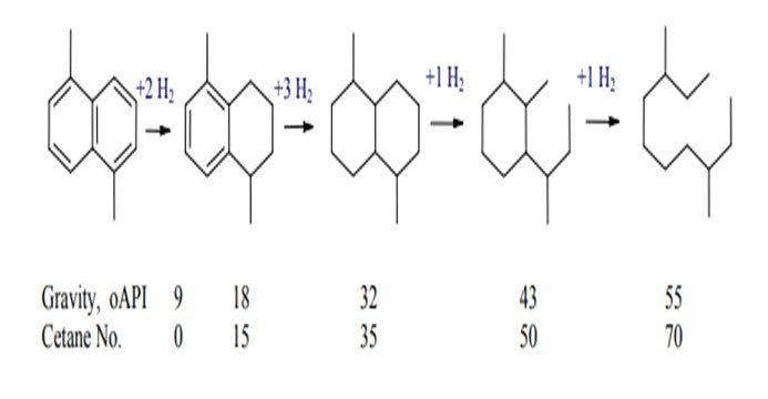
The reaction system illustrated below shows the substantial improvement in density and cetane quality as a consequence of aromatic saturation. The addition of hydrocracking ring-opening chemistry provides substantial incremental improvement with a relatively modest incremental cost of hydrogen.
The sequence of aromatic saturation and ring opening will give a reduction in boiling point of as much as 100o F. This very large reduction in boiling point means that extra gas oil boiling above the normal diesel cut point can be recovered and then shifted into the ULSD product pool.
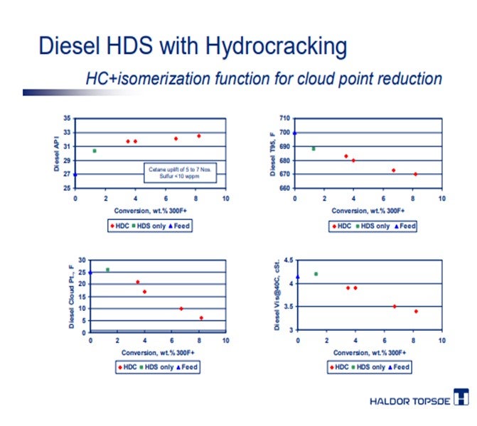
Haldor Topsoe can offer catalyst formulations that give both conventional hydrocracking performance and also hydrocracking with enhanced isomerization function to improve the cold flow properties of the distillate together with cetane improvement and end point shifting. An example of this performance is shown in the figures below. A high density (27o API) high end point (700o F T95) gas oil feedstock is first desulfurized to ULSD level and then hydrocracked over catalyst with enhanced isomerization function. At modest levels of conversion to naphtha, the density, distillation, cloud point and viscosity of the feed are improved significantly.
Hydrocracking catalysts can be applied in stacked systems with hydrotreating catalysts under moderate pressure levels as low as 700 psig in the reactor. A key consideration is the HDN performance of the pretreating catalyst allowing deep hydro-denitrogenation in addition to deep hydro-desulfurization. The proper allocation of both hydrotreating catalyst and hydrocracking catalyst will optimize performance and cycle life.
Haldor Topsoe can offer both CoMo and NiMo catalysts with the highest activity for deep HDS and HDN in the refining industry. Further product uplift can be achieved by the application of hydrocracking and isomerization chemistries utilizing Topsoe’s Hydrocracking and dewaxing catalysts specifically designed for heavy distillate upgrading.
Martin Gonzalez (BP)
Hydrogen supply and compression constraints are becoming more common for refineries in the US as more and more bitumen-based crude is brought in from Canada. These crudes are hydrogen-deficient and their processing commonly leads to a greater volume of coker products, which will also have high hydrogen uptake in a hydrotreater. For this reason, a refiner may be forced to sacrifice hydrogen uptake in FCC feed for the sake of producing ULSD, or vice versa, and refiners are increasingly looking for handles that will enable them to make this trade-off.
Where hydrogen supply in a refinery is constraining, H2 consumption in diesel and gas oil hydrotreaters can be manipulated by varying feed rate, feed composition, reactor temperature, and/or reactor pressure. Lowering pressure and temperature in a hydrotreater will generally raise product sulfur and reduce hydrogen consumption. In FCC pre-treat service, lowering reactor temperature and/or pressure to free up hydrogen will result in a lower yield of FCC naphtha, and such naphtha will have a higher sulfur content. In ULSD service, reducing hydrogen consumption will worsen product cetane and sulfur.
Thus, the key factor in deciding whether to utilize hydrogen for FCC pre-treat vs. ULSD relates to the economics of gasoline production in comparison to diesel. When a gasoline blend is constrained on octane or sulfur, FCC pretreating feed may be favored. Likewise, a cetane or sulfur constraint in a ULSD product may make it attractive to divert more hydrogen into diesel treating service. Finding the optimum balance usually requires a refinery linear program that is tuned for hydrogen consumption and sulfur removal. In high pressure units, NiMo catalysts will generally promote a higher hydrogen uptake, while CoMo can promote sulfur removal at a lower hydrogen uptake.
Tim Lewer (Shell)
The criteria are set by balancing the product specifications and positive economics from volume gain and/or FCC conversion with H2 availability. A minimum amount of H2 consumption is required to achieve the ULSD sulfur and Cetane specs and to maintain the FCC feedstock sulfur for low sulfur gasoline production. The volume gain by enhancing the hydrogenation activity of the ULSD catalyst system or improved product quality through dewaxing must be compared to the improvement in FCC conversion, reduction in LCO production, and reduced gasoline post treatment severity by enhancing the hydrogenation and hydro denitrification of the FCC Pretreat catalyst system or the addition of conversion through Mild hydrocracking.
In the ULSD unit, stacked bed catalyst loadings with CoMo and NiMo catalysts enable a tailoring of the performance and H2 consumption to meet the determined economic drivers. Selective placement of the NiMo catalyst is critical to meeting the optimized H2 consumption. The inclusion of Dewaxing catalyst may alter the stacked or sandwich loading to accommodate ULSD production with less hydrotreating catalyst while properly preparing the feed for dewaxing.
In the FCC Pretreat unit, stacked bed loading of CoMo and NiMo catalysts should be combined with reactor temperature profiles that promote the desired extent of hydrogenation. The addition of mild hydrocracking catalyst requires a shift to additional NiMo catalyst for increased HDN performance.
Kaspar Vogt (Albemarle)
The minimum hydrogen consumption is set by the mandatory ULSD specifications in diesel hydrotreaters and in FCC pretreat (FCC-PT) typically by the FCC naphtha sulfur. Any additional hydrogen can be added to the product and can be financially beneficial to the refinery. In diesel additional H2 can be used to process worse feeds and/or produce higher Cetane lower density product. In FCC-PT additional hydrogen can improve the feed to the FCC unit resulting in better yields, improved product properties and less FCC catalyst usage. Per refinery the optimum usage of H2 needs to be calculated.
Unsurprisingly, no single catalyst formulation is able to deliver optimum performance across the wide variety of feeds and process conditions used in ULSD and CFHT service. By necessity, a series of catalysts, each having its optimal application window, is able to deliver the best balance of superior activity and stable operation. Proper catalyst selection balances the objectives of the unit (desulfurization, denitrogenation, cetane uplift, aromatic saturation) with the capabilities of the unit (hydrogen partial pressure, hydrogen availability) to maintain stable performance throughout the cycle. NiMo vs. CoMo catalyst at the same product sulfur can consume around 10% more hydrogen. By applying multiple catalysts in STAX® configurations, the hydrogen consumption can be minimized while still capturing the activity benefit.
Greg Rosinski (ART)
For any given feed, hydrogen consumption is a function of hydrogen partial pressure, LHSV, H2/Oil and catalyst. For the most part, the first three variables are fixed for a given unit, since throughput reduction is not an economical choice. Thus, catalyst selection is one of the few constraints which refiners are willing consider.
CoMo catalysts have lower hydrogen consumption than NiMo catalysts due to lower aromatic saturation activity. At equivalent product sulfur, using all CoMo catalyst in the FCC Pretreater will lower the hydrogen consumption with a longer cycle in terms of HDS activity, but at the cost of lower conversion in the FCC and higher LCO yields. Using all NiMo catalyst in the FCC Pretreater will result in higher FCC gasoline yields and lower LCO yields due to higher PNA saturation, but a shorter cycle life in terms of HDS activity.
With regards to the ULSD units, if the unit is high pressure, using a NiMo catalyst will result in higher aromatic and PNA saturation. This may be beneficial if cetane upgrade is desired; however, there may be a diminishing return on hydrogen for the incremental cetane upgrade over a CoMo catalyst.
ART can help optimize both FCC Pretreater and ULSD performance based upon the refiners needs, including hydrogen consumption, cetane uplift and cold flow properties. ART provides the ApART and SmART staged catalyst systems for FCC Pretreat and ULSD applications, respectively. ART has helped many refiners manage hydrogen consumption in both units by using staged catalyst systems utilizing NiMo, CoMo and NiCoMo catalysts optimized to enhance HDS, HDN or HDPNA activity for a given feedstock. Furthermore, ART’s relationship with Grace Davison can further enhance the unit optimization to include the FCC unit as well as the FCC pretreater and the ULSD unit. Utilizing the technical resources of both ART and Grace Davison, the refiner can gain a more comprehensive understanding of the interactions and dependence of these units on each other in terms of hydrogen consumption and product property enhancement.
Raj Patel (Haldor Topsoe, Inc.)
With a limited supply of hydrogen, the refiner will always look for ways to optimize the consumption in the different hydrotreating units. In this context “optimization” frequently means minimization, but the value-adding effect of hydrotreating through volume-swell, improved product properties and improved performance of downstream units (e.g. better conversion and product distribution in the FCC when the feed has been pre-treated) should also be taken into account. Generally, in all units there will be a minimum hydrogen consumption, given the constraint that the product must meet certain specifications. This hydrogen is mainly consumed by HDS and hydrodearomatization (HDA) reactions and to lesser degree by saturation of olefins, HDN reactions and hydrocracking. However, due to the above mentioned positive effects of hydrogen addition as well as unit configuration and feed properties, one will often have a certain operating window within which it is possible to reach production targets. Even so, the hydrogen consumption often decreases from SOR to EOR, and as product specifications must be met even at EOR there is typically a give-away at SOR. In other words, the hydrogen consumption is higher than actually required at SOR. Topsøe markets the Reverse Shift process to alleviate this problem. By this process hydrogen consumption is more or less constant throughout the cycle and thus a substantial saving at SOR is achieved.
The most important knobs that one can turn to change hydrogen consumption are unit pressure, feed properties, catalyst selection, product specifications and operating strategy. An overall economic evaluation of both the ULSD and the FCC complex should be made to closely determine optimal usage of hydrogen before these knobs are turned and a thorough understanding of consequences is needed to determine optimal configuration. A higher partial pressure of hydrogen will increase hydrogen consumption through higher aromatic saturation but also increase catalyst lifetime. Feed properties are usually fixed, but in some cases feed tailoring can significantly reduce hydrogen consumption without compromising overall economics. The catalyst selection is critical to achieving profitable operation, as considerable changes can be made from e.g. changing from CoMo to NiMo type catalysts. Generally, the CoMo type catalysts (such as TK-578 BRIMTM) use less hydrogen than NiMo type catalysts (such as TK-607 BRIMTM), but the feed reactivity (content of sterically hindered sulfur species and nitrogen inhibitors) may force the use of either CoMo or NiMo if the required HDS conversion must be met. The exact impact on hydrogen consumption for different catalyst, feedstock, process conditions and operating strategy requires detailed model of the chemical reactions occurring in the reactor. Both kinetic and equilibrium limitations must be properly described and Haldor Topsøe has developed models from fundamental knowledge of catalyst reactivity and reaction modeling that allow for optimizing the unit economy.