Benjamin Harris
Former Assistant Secretary for Economic Policy and Chief Economist of the Treasury Department
ESTEBAN (Suncor Energy, Inc.)
I have a lengthy description of LOPA itself to help address this question. Layers of Protection Analysis is the structured process used to determine the appropriate layers of protection required to provide adequate safeguards for adverse and sometimes catastrophic events in process units. As part of our Process Hazard Analysis standard at Suncor Energy, we follow LOPA as defined by the 2001 Center for Chemical Process Safety Concept of Layers of Protection Analysis. The LOPA process targets a ratio of 1:1 between the acceptable frequency of an event and the likelihood of the event.

The acceptable frequency of an event is inversely correlated to the risk ranking of the event and is displayed as the target mitigated event level, or TMEL. The event is evaluated for potential consequences without any safeguards in place and risk-ranked according to the Suncor Risk Matrix to determine the TMEL. The intermediate event likelihood, or IEL, is determined by multiplying the initiating cause likelihood (ICL) with the probability of failure on demand (PFD) of each of the independent layers of protection. The intermediate event likelihood can be calculated using other risk-reducing factors called conditional modifiers (CM) and enabling factors (EF); however, it is Suncor’s practice to be conservative and assume the factors are equal to one.

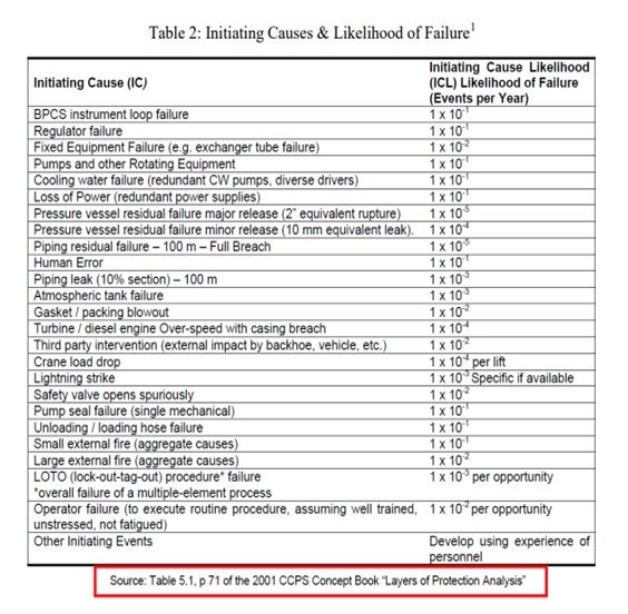
Slide three is simply a shot from the Safety Concept Book that shows initiating cause likelihoods and their likelihood of failure.

Slide four shows the probability of failure on demand for independent layers of protection. While the event likelihood can be easily defined using values provided in the text, the evaluation of the event consequences is an experience-based conjectural process. In order to appropriately determine consequences, it is important to have unit-specific and/or project-specific knowledge and experts as part of a PHA team to provide insight to the individual characteristics of the specific process in question.

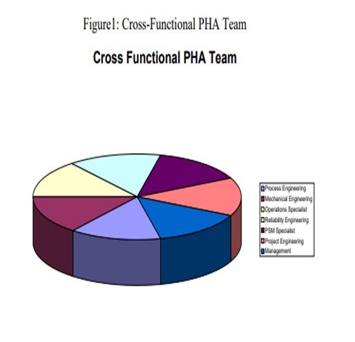
In addition to process expertise, it is often critical to have a wide variety of members on the team, including those who can provide expertise on fixed equipment, rotating equipment, and process safety management. At Suncor, we typically attempt to build PHA teams with cross-functionality in order to provide the most accurate evaluation of event consequences. For example, at the Denver Refinery, with the recent revamp on our gas oil hydrotreater, we had a very diverse cross functional PHA team to provide the most appropriate evaluation. The revamp project provided additional heat exchange in the reaction and fractionation section, tray and tower modifications, an integrated pump around circuit, and heater modifications to allow for increased severity operation. A cross-functional PHA team included the PHA facilitator, PSM (process safety manager), area safety representative, project manager, project engineer, project and area process engineers, chief and unit operators, project mechanical engineer, project metallurgist, and project rotating equipment engineer.

LEICHTY (Chevron USA, Inc.)
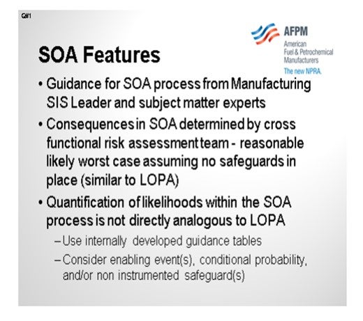
Chevron does not use LOPA in PHA studies. We have an internal process called the Safety Objective Analysis that we do for all new units or existing units being evaluated for safety instrumented systems. Our method is similar to the LOPA, but there are differences.
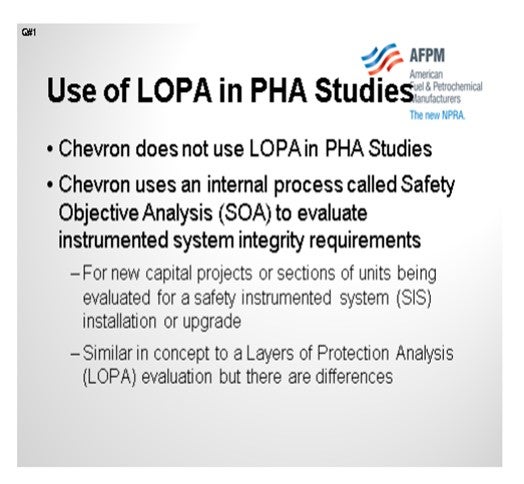
The guidance that we have for this process comes from our Global Manufacturing Safety Instrumented System Leader and subject matter experts in the various process technologies. The method of determining consequences in the Safety Objective Analysis is similar to that determined by the LOPA. However, the quantification of likelihoods in the Safety Objective Analysis is not analogous to LOPA. For the likelihood analysis, we use internally developed guidance tables and consider enabling events, conditional probabilities, and non-instrumented safeguards.
ESTEBAN (Suncor Energy, Inc.)
Suncor Energy, Inc. employs the use of Layers of Protection Analysis (LOPA) in our OSHA-required Process Hazards Analysis (PHA). The Layers of Protection Analysis is typically performed following the Hazard and Operability Study (HAZOP) which ultimately provides a comprehensive list of potential scenarios and their corresponding consequences assuming no safeguards are in place to mitigate an event. The potential consequences identified in HAZOP are based on the experience and knowledge of the PHA attendees, including general industry knowledge as well. That is one of Suncor’s drivers for large cross functional PHA teams when performing whole unit and major project PHA evaluations. While Suncor currently does not have a corporate standard set of consequences for given scenarios, it is our intent to develop a standard that will drive consistency company-wide. The figure below depicts an example of cross functional PHA team members used for a revamp project on a gas oil hydrotreater.
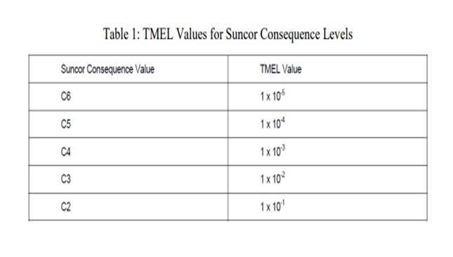
Individual scenarios consequences are ranked in severity from low C1 to extremely high (catastrophic) C6 in accordance with our corporate risk matrix. Events with consequences at or above a threshold value of C4 are then evaluated using LOPA. In order to perform a LOPA an accepted frequency level for the event is established using correlated values for consequence rankings. Table 1 depicts the correlated acceptable frequencies as a function of consequence ranking. The acceptable frequency is presented as the target mitigated event levels (TMEL) which are values defined in terms of the consequence occurring per year or the probability of the consequence occurring in so many years. For example, a TMEL value of 1 X 10⁻⁴ is equivalent to the frequency or probability of occurring must not exceed 0.0001 times per year or 1 time per 10,000 years.
Each event is then associated to an initiating cause and the initiating cause likelihood (ICL) is assigned. The ICL is defined as the likelihood of failure in events per year given a certain initiating cause. The following Table 2 is used to define initiating causes and corresponding ICL values.
Following assignment of and ICL each event is evaluated for enabling factors (EF) and conditional modifiers (CM) as defined by CCPS LOPA text pages 67 and 33-40 respectively. However, at Suncor Energy, Inc. in accordance with our corporate standards we do not allow the application of enabling factors and conservatively do not apply conditional modifiers.
1 “Layer of Protection Analysis: Simplified Risk Assessment”; Chemical Process Safety (CCPS) Concept Book; American Institute of Chemical Engineers (AIChE) Centre for Chemical Process Safety (CCPS), 2001, p71. 2012
In order to achieve adequate layers of protection to reduce the probability of events as defined by the TMEL of the event, independent protection layers (IPL) are applied to the scenario. Each independent protection layer has a predetermined probability of failure on demand (PFD). This PFD defines the probability of risk reduction applied to the scenario for each given layer of protection. Table 3 displays the PFD values for given independent layers of protection.
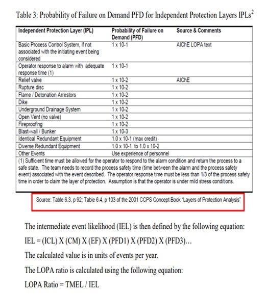
A LOPA ratio of 1 or greater identifies and event that has adequate layers of protection, while a LOPA ratio of less than one identifies an event that requires additional layers of protection be defined or recommended to mitigate the probability of event consequences.
2 “Layer of Protection Analysis: Simplified Risk Assessment”; Chemical Process Safety (CCPS) Concept Book; American Institute of Chemical Engineers (AIChE) Centre for Chemical Process Safety (CCPS), 2001, p103
BODOLUS (CVR Energy)
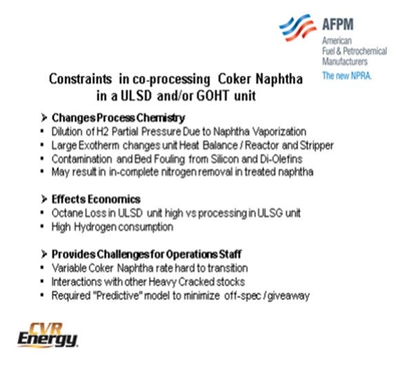
There are some constraints relative to processing coker naphtha. I have outlined a few of them on the slide. Key with coker naphtha are the changes in the process chemistry that occur starting, perhaps, with the dilution of the hydrogen partial pressure due to the vaporization of the naphtha. Vaporization of the naphtha dilutes that vapor space. There is also coker naphtha having a large exotherm. I refer to it a lot with the Operations staff as it is almost like a match for your process. The coker naphtha starts the exotherm off very early at the topmost parts of the bed, and you have to control that exotherm through the rest of the reactor. The exotherm imposes changes in reactor dynamics, in terms of temperature control and any of the other peripheral equipment that might be heat-integrated with the reactor. It also recovers the naphtha material that has been processed in the stripper tower. One issue associated with contamination is bed fouling due to silicon and diolefins. There is a liability with the coker naphtha if the naphtha is routed to the reformer pool because it might not get out all of the nitrogen. You may wind up looking at enhanced nitrogen levels in your reformer area.
Our economic effects: Octane loss in a distillate hydrotreater is high due to saturation of all of the olefins. Coker naphtha processed in an ultra low sulfur gasoline unit will preserve those olefins and result in less octane degradation. Processing coker naphtha comes at a liability of high hydrogen. It takes a lot of hydrogen to process the coker naphtha. In particular, though, in our unit on which we did a revamp in 2008, the rates of the coker naphtha and of other cracked stocks in the unit presented some interesting challenges to the operators. We found that the interaction with other heavy cracked stocks was complicated, so to speak. We look forward to trying to get a predictive model to help the Operations staff run the unit.
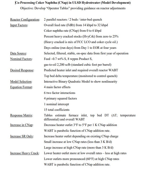
This slide shows our model covering the two parallel reactors with two beds in each reactor and an inter-bed quench. We had multiple feedstocks coming from multiple sources: some cracked and some straight run, including coker cycle oils and light cycle oils. Of course, the coker naphtha varied in many proportions. I do not want to say on a daily basis; but when we had a lot of different cracked stocks in a unit and the units going up and down were changing the rates, the operators had to jockey all of these particular variables. It is somewhat difficult for them to understand how to change all of the conditions.
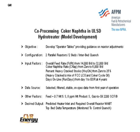
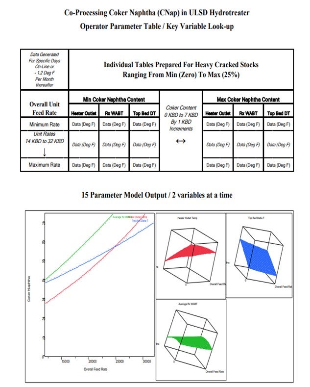
We were looking for an attainable response. In order to cover all of the interactive parameters, we elected to cover those with at least six interactive factors and four primaries squared. When we had about 15 different coefficients in the model, we looked at what the operators monitor. It was a limited slate of furnace inlet, top bed ΔT (temperature differential), and overall WABT (weighted average bed temperature) on the unit to get to spec. The modeling more or less showed quite a few interactive variables and quadratic surface responses. We found that it was not necessarily a linear function of the addition of some of these variables. Over the years, my experience has been that your typical board operator can handle two, three, or four variables at a time. But when you have multiple variables with multiple nonlinear interactions, it is difficult for him to perceive how to change the unit ahead of time preemptively, so a tool is required.
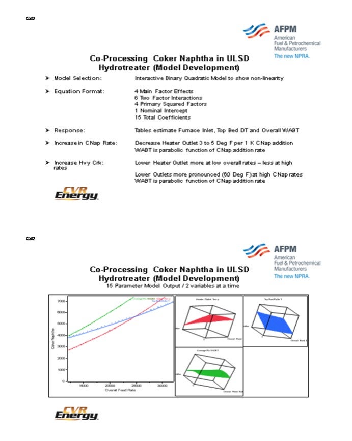
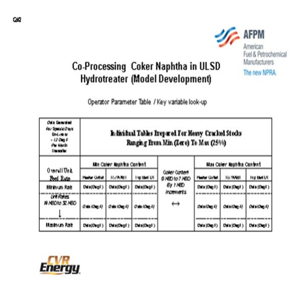
These types of graphs are not what you would share with the Operations staff, so we boiled them down to a set of tables. It is an old-school look-up. I mean, if people would say, “Well, just plug the numbers into the computer; it will tell the operators what to do,” that would cut the amount of the long-term understanding of the variables and their interactions. So we prepared tables with a date stamp, and then the tables got up periodically. The tables contained most of the variables, so the operators were able to page through and read across on the table. It seemed to help them adjust the unit proactively to be on spec.
LEICHTY (Chevron USA, Inc.)
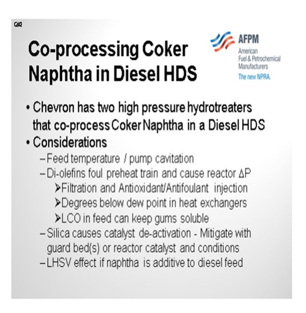
Chevron has two high pressure hydrotreaters that co-process coker naphtha in a diesel service. The other feedstocks are coker light gas oil and FCC (fluid catalytic cracking) light cycle oil. Both units feed 100% cracked feed stocks.
Considerations: Beginning with the feed pump, the addition of coker naphtha must not create a mixture at the feed pump suction conditions such that the vapor pressure results in cavitation. Moving on to the preheat train, we find that diolefins in the feed can result in polymerization fouling. In some cases, an antioxidant injected into the coker naphtha rundown, combined with an antifoulant in the total unit feed, can mitigate the fouling. Also, we found that if the naphtha content is too high in the feed, accelerated fouling can result. We monitor this fouling by calculating the degrees below dew point in the preheat exchangers. This fouling may be due to lower stability or solubility of gums as the mixture partially vaporizes through the exchangers. We have also determined that the presence of LCO (light cycle oil) in the feed can sometimes help keep gums and other polymerization products soluble, thereby mitigating furnace and/or exchanger fouling. In the reactor, silica poisoning of the catalyst can be mitigated through the use of some of the newer generation coker antifoams containing lower silica content. If the silica is from another source, a guard bed may be necessary to achieve the desired run length. With respect to desulfurization of the diesel, there may be a negative space velocity impact if the naphtha feed is added to the existing diesel range feed.
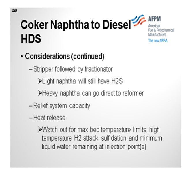
Additional Considerations: In order to effectively strip H2S (hydrogen sulfide) from the product and separate the naphtha from distillate, a stripper column followed by a fractionator is an effective configuration. Note that even with this configuration, the naphtha will still contain some H2S; but, the H2S content can be made low enough to feed directly to a reformer. Another important aspect to consider is the ability of the relief system to handle the addition of coker naphtha. A relief system study should be performed to ensure adequate capacity. Lastly, but most importantly, the olefins in the coker naphtha cause high heat release in the reactor, temperature control challenges, and high hydrogen consumption. If not properly managed, the effluent train temperature profile could change such that the location of the metallurgy switch between carbon and stainless steel is no longer adequate to protect against high temperature hydrogen attack and high temperature sulfidation. These two corrosion mechanisms can lead to catastrophic failure. In addition, the higher temperature in the effluent train may reduce the percent liquid water remaining at the continuous water injection point, which can lead to a failure in the reactor effluent air cooler below the 25% minimum guideline.
JEFF JOHNS (Chevron Products Company)
I think we are letting the panelists off a little too easy, so I will ask a question. Does the coker naphtha that you mentioned include the C5/C6 portion, sometimes called PenHex? If it does, can you comment on a specific experience you have had with that portion of the naphtha?
LEICHTY (Chevron USA, Inc.)
We do have coker C5 and C6s (coker PenHex) contained in the coker naphtha that is fed to our distillate hydrotreaters. These low boiling point molecules contain a higher percentage of olefins and are the most reactive; therefore, they are more challenging, from a fouling and reactor heat-release perspective.
BODOLUS (CVR Energy)
Our coke naphtha contains it as well. We process it as we get it.
ALAN WELDON (Hunt Refining Company)
What do you consider a high percentage of cracked coker naphtha versus just diesel?
BODOLUS (CVR Energy)
High would be on the order of 20%, perhaps.
LEICHTY (Chevron USA, Inc.)
Limits could be encountered in several sections of the unit, as discussed in the considerations mentioned previously. If the maximum reactor bed/total temperature rise is the only limiting factor, then 35% coker naphtha can be achievable.
BODOLUS (CVR Energy)
The primary operating constraints in co-processing coker naphtha in a heavy oil hydrotreaters concern dilution of hydrogen partial pressure (due to naphtha vaporization) and the effect that the exotherm has on the unit heat balance. Inclusion of coker naphtha increases the top bed exotherm, often reducing heater duty. Simultaneously, there may be an increase in stripper section duty to lift the product naphtha into the overhead stream.
Primary contamination constraints in coker naphtha include silicon resulting from the decomposition of antifoams used during the coking process. The silicon contamination deposits on the hydrotreating catalyst leading to deactivation and has a severe negative impact on the prospects of regenerating the spent catalyst. Top bed fouling, due to diolefin content of coker naphtha, can also limit run length due to differential pressure build. If the unit is expected to have a steady diet of coker naphtha, catalyst loading options in the top bed can include a silicon trap and/or a layer of controlled diolefin saturation catalyst along with enhanced void bed grading. Note that coker naphtha holding tanks should be protected from oxygen ingress, which produces peroxy free radicals, and long-term storage at elevated temperatures due to olefin/diolefin content.
From an economic standpoint, coker naphtha processing in a distillate hydrotreaters also causes a loss of octane due to saturation of olefins. Consumption of hydrogen will be high and resulting treated naphtha may have residual nitrogen liability. Other processing options, such as co-processing in an ultra-low sulfur gasoline hydrotreater, can preserve octane values and allow treated coker naphtha to enter the gasoline pool (preventing nitrogen liability on the reformer).
Balancing the heat duty and overall rate changes in heavy oil hydrotreaters with variable coker naphtha is not always intuitive to the operations staff. After a more than a year of operations it was decided to develop a transition tool to assist operators in “Predicting” what new heater setting would be required with a rate change in any of the feedstocks (coker naphtha, FCC light cycle oil, coker cycle oil and straight run diesel).
The following slides and tables show how selected process variables were chosen to develop a model for the operator to “Predict” reactor parameters necessary to minimize off-spec product and reduce giveaway.
KASPAR VOGT and STEVE MAYO (Albemarle Corporation)
Coker naphtha is typically high in sulfur, nitrogen, diolefins and silicon. It often also contains significant amounts of arsenic and in some cases particulates from the coker and iron scale. Treating coker naphtha is much more challenging than straight run naphtha, even when it is blended with straight run naphtha. For these reasons, refiners are sometimes tempted to treat coker naphtha in higher pressure units with a heavier feedstock such as diesel or VGO (vacuum gas oil). This can be done successfully, but there are caveats to consider before embarking down such a path:
• The addition of a lighter feed component that fully vaporizes will reduce hydrogen partial pressure, potentially reducing the unit’s performance with regard to its primary feedstock.
• The introduction of olefins and diolefins may result in higher exotherms, as well as increased hydrogen consumption. As a consequence, hydrogen partial pressure will be reduced and potentially also the operating window for the unit. When possible, coker naphtha used as a liquid quench can alleviate its exotherm by heat of vaporization. A downside is introduction of catalyst poisons in the lower beds of the hydrotreater.
• Poisons such as As (arsenic) and Si (silicon) will be introduced to the unit and may require a more extensive guard bed system to handle them. A larger portion of the reactor devoted to guard bed catalyst will reduce the volume available for main bed catalyst and could impact cycle length.
• In particular for ULSD, the most difficult sulfur compounds require hydrogenation before they can be desulfurized. Adding coker naphtha, with its typically high N (nitrogen) content, increases organic nitrogen into the reactor and may increase the level of nitrogen inhibition of catalyst active sites. This disproportionately affects hydrogenation sites and effectively reduces the rate of removal of the most difficult sulfur compounds.
• VGO units, with their typically lower LHSV (liquid hourly space velocity) and higher hydrogen partial pressure, are better equipped to handle the introduction of coker naphtha. However, the naphtha will operate in the vapor phase and may encounter diffusion issues with the VGO operating in liquid phase, reducing the rate of sulfur and nitrogen removal.
• The fractionated naphtha stream will be too high in mercaptans (due to recombination) to send directly to the reformer and will need to be post-treated
MEREDITH LANSDOWN, BRIAN WATKINS, and BRIAN SLEMP (Advanced Refining Technologies)
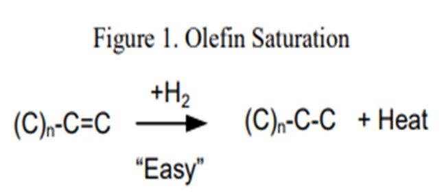
Co-processing coker naphtha in ULSD service can have several undesirable effects on the performance of the hydrotreater and the catalyst if the system was not properly designed to handle it. In general, coker stocks have a higher level of olefins present from the coking process. Once in the hydrotreater these olefins will quickly get saturated (Figure 1) consuming additional hydrogen and generating extra heat. As a general rule of thumb, one mole of hydrogen is required per mole of carbon/carbon double bond, or between five and 10 times the bromine number reduction in standard cubic feet of hydrogen per barrel (scfb). This additional heat (130 BTU/scf (British thermal unit per standard cubic foot) to 160 BTU/scf hydrogen consumed), if not spread out through a decent portion of the catalyst bed, will initiate the subsequent reactions creating a much higher temperature rise than expected. This excess temperature can also speed up the coking or polymerization mechanism which will lead to an increase in pressure drop. This can set an upper limit as to how much coker naphtha can be processed either by a need to limit the heat rise, or from too much hydrogen consumption that could starve the downstream catalysts.
A system that is properly size and activity graded will be extremely important when co-processing coker naphtha in a diesel unit. ART utilizes a grading system to help mitigate pressure drop build-up. ART’s GSK-19 is a 19-mm inert ring with a very high void fraction used for trapping large particulates and is placed at the top of the reactor. GSK-9 is loaded next and is a 9-mm macro-porous ring that traps iron, as well as other finer particulates that can increase pressure drop. ART also utilizes two other types of active grading, GSK-6A and GSK-3A, which are smaller rings with a small number of active metals present in order to begin any olefin saturation reaction, as well as provide additional void space at the top of the reactor. Underneath the grading options, it is recommended to use a layer of ART’s AT724G or AT734G which can provide both additional olefin saturation, additional void fraction for pressure drop mitigation, as well as a trapping mechanism for silicon (and arsenic), which is another concern with co-processing coker naphtha in a ULSD unit.
Another major concern is that coker naphtha can also bring silicon into the unit which is a permanent poison for hydrotreating catalyst. A silicon guard, such as ART’s AT724G or AT734G, should be loaded in the reactor to mitigate silicon poisoning. Silicon pickup is temperature dependent, and at the higher temperatures ULSD units are operating at, silicon pickup in the order of 16 wt% to 25 wt% could be expected with AT724G or AT734G. If arsenic is present in the coker stocks, the use of AT734G is preferred as it will have the same silicon pickup as AT724G and will also protect the active catalyst against arsenic poisoning.
A third concern is the high degree of vaporization of the coker naphtha. ULSD hydrotreaters are typically designed such that their feed distribution system will contain liquid, and the additional gas present from the coker naphtha may cause some systems to perform poorly giving rise to maldistribution. In order to minimize feed vaporization and poor distribution tray utilization, the coker naphtha should be mixed with the other feed streams at a temperature where it is still liquid before feeding to the charge heater. The recovery system should also be evaluated for the increase in naphtha that will be present so that the downstream equipment is not overloaded.
A final consideration would be that additional coker naphtha in a diesel can generate incremental dry gas products such as methane and ethane. These products will increase in concentration in the recycle gas loop, causing a decrease in the hydrogen partial pressure for the hydrotreater. It will also increase the molecular weight of the recycle gas, which can lead to compressor capacity limitations. These additional products can also lead to incremental stripper off-gas and related problems.
PAUL CECCATO (Criterion Catalysts & Technologies)
Several factors should be evaluated when considering the co-processing of coker naphtha in either ultra-low sulfur diesel or FCC pretreat units. Changes to the hydrogen partial pressure, hydrogen consumption, reactor fouling, reactor temperature profiles, fractionation capabilities, and catalyst deactivation will impact both types of operations. Ultimately, the selection of were to co-process coker naphtha is based on the relative impacts of these factors on each unit.
Co-processing coker naphtha reduces hydrogen partial pressure due to the vaporization of the naphtha range material and increased hydrogen consumption through saturation of its high diolefin/olefin content. A reduction in hydrogen partial pressure directionally reduces heteroatom conversion, aromatic saturation, and catalyst stability. In a ULSD operation, treating the more sterically hindered sulfur species with less hydrogenation activity becomes more difficult, limiting the feed endpoint and the percentage of cracked stock in the feed blend. In an FCC pretreat unit, reductions in nitrogen and aromatic conversions directionally lower FCC conversion.
As the hydrogen partial pressure decreases, aromatic equilibrium and condensation occur at lower temperatures. For a ULSD unit, cycle life may shorten due to increased coking and insufficient hydrogenation activity at elevated temperatures. In FCC pretreat operations, cycle life also declines due to accelerated catalyst deactivation as larger aromatics condense to coke at lower temperatures.
Saturation of the diolefins and olefins introduced with coker naphtha consumes significant hydrogen, depleting excess hydrogen at the reactor outlet. ULSD or FCC pretreat units operating with marginal hydrogen treat gas-to-makeup ratios may experience hydrogen starvation and accelerated catalyst deactivation. Insufficient excess hydrogen may also result in lower bed pressure drop issues when processing cracked stocks in either the ULSD or FCC pretreat units or high asphaltene feeds in the FCC pretreat unit due to rapid coking.
Polymerization of the diolefins/olefins in the coker naphtha may lead to increased reactor fouling and upper bed pressure drop. Typically, neither ULSD nor FCC pretreat units are designed with low temperature lead reactors for mild saturation of the highly reactive diolefins. Competition for active catalyst sites at the top of a reactor may leave diolefins and olefins unsaturated and exposed to elevated temperature which drives polymerization.
Heat release from diolefin and olefin saturation is significant and may result in a more ascending temperature profile in a single bed reactor and increasing quench requirement in a multi-bed reactor. Maintaining preferred equal bed outlet temperature profiles can become difficult as quench is diverted upward in the reactor. Radial temperature spreads in reactors with older reactor internals may increase with the increased axial delta T (temperature differential) and push established operating limits, constraining the reactor inlet temperature.
Delayed coker naphtha typically contains varying quantities of silicon from antifoam addition. Si is a poison to hydrotreating catalyst with a larger impact on the denitrification function. Reactor loadings can be adjusted to include high capacity Si trap catalyst at the expense of high activity catalyst volume. In a ULSD unit, Si induced catalyst deactivation impacts cycle life. In the FCC pretreat unit which typically contains more catalyst volume, the Si impact is less; but when combined with other metals induced deactivation, cycle life may be impacted or a reduced.
Lastly, co-processing coker naphtha requires sufficient fractionation capabilities to recover the naphtha product. Poor fractionation in a ULSD unit may result in heavy naphtha contamination of the diesel product for lower cetane. Poor fractionation in the FCC pretreat unit may result in insufficient naphtha recovery and the reprocessing of an increased diesel draw through the ULSD unit.
The impacts of co-processing coker naphtha in a ULSD or FCC pretreat units should be evaluated individually and compared to unit constraints and objectives. Ultimately, the selected unit will be capable of minimizing the impacts.
ESTEBAN (Suncor Energy, Inc.)
The increased desulfurization of distillate fuels removes sulfur nitrogen and aromatics, which are components favorable for lubricity properties. The recent market conditions have led most refiners to not only produce ULSD, but also ULSK (ultra low sulfur kerosene), in order to maximize distillate production. At Suncor, we have been driving our facilities to maximize the distillate. We often do not take advantage of the minor impacts that could come from flexibility with feed streams and blend components, or even minor impacts from changes in reactor loadings, in order to have some difference on our finished product lubricity. The level of hydrotreating required to meet sulfur specifications on distillate fuels removes and/or changes so many trace components good for lubricity that it is much more economical to use lubricity additives to maximize refinery yields.

At the Denver Refinery, we produce commercial Jet A, which is a non-additized fuel. There is no lubricity specification for that particular fuel. We produce Jet A using similar blend components to #1 ULSD, which allows us to minimize our overall storage requirements. While Jet A is the only product that we produce, there are jet fuel products with lubricity specifications that we do not produce for military use. Those fuels are additized.

LEICHTY (Chevron USA, Inc.)
Straight run fuels have good lubricity due to the presence of trace compounds containing sulfur, nitrogen, and oxygen. These compounds are removed by hydroprocessing. Because it is impossible to predict the lubricity based on bulk properties, lubricity must be measured using the BOCLE (Ball-on-Cylinder Lubricity Evaluator) test. Fortunately, modern engines are designed for low lubricity fuel and can burn Jet A, which has no lubricity specification. However, other grades of jet fuel may require additives to improve lubricity. These additives also act as corrosion inhibitors.

Chevron operates facilities where the finished jet products are 100% hydrotreated and/or hydrocracked. These products include Jet A, Jet A-1, and JP-8. The testing and additive requirement depends on the fuel. When additizing, it is possible to optimize the response and dosage by doing testing ahead of time. There are three approved additives: Nalco 5403, Innospec DCI-4A, and Afton HiTEC 580.

For Jet A, there is no lubricity testing requirement.
For Jet A-1, lubricity testing is required if any of the following four conditions are met:
1. The fuel is derived from greater than 20% severely hydrotreated material, meaning that it is hydroprocessed at a pressure greater than 1015 psi (pounds per square inch).
2. The fuel is made from greater than 95% hydroprocessed material.
3. The fuel is synthetically derived, i.e., Fischer-Tropsch reaction-derived material.
4. The wear scar by the BOCLE test is greater than 0.85 mm (millimeters).
For JP-8, additives are required regardless of processing condition.

AHMAD AL-JEMAZ (Kuwait National Petroleum Company)
A question on ULSD protection: Do you have any experience having a reactor with both hydrotreating and dewaxing beds in one reactor?
LEICHTY (Chevron USA, Inc.)
Yes. We do have one unit with that has a dewaxing catalyst layered into the hydrotreating catalyst.
AHMAD AL-JEMAZ (Kuwait National Petroleum Company)
So, there is a robust design that you can rely on that enables you to do without the lubricity additives?
LEICHTY (Chevron USA, Inc.)
We have not had any issues with this unit.
SUBHASH SINGHAL (Kuwait National Petroleum Company)
Is it preferable for these lubricity additives to be added inside or outside of the battery limit? What is the usual preference of the refiners if there are lubricity additives inside the ULSD unit, or it is done outside in tankers area?
ESTEBAN (Suncor Energy, Inc.)
We have our additives downstream of blending, so they go in with the finished fuel.
DAN WEBB (Western Refining)
Does anyone have experience co-processing jet or pulling a jet stream off of the ULSD unit stripper or fractionator, especially in light of the previous discussion of co-processing coker naphtha?
ESTEBAN (Suncor Energy, Inc.)
Our ULSD unit in Denver pulls a sidecut of kero (kerosene). Typically, that is then either blended back into the diesel stream or, in some cases, used as a jet blend stock.
DAN WEBB (Western Refining)
How does that process scheme affect your jet products, as far as lubricity and any of the other specs?
ESTEBAN (Suncor Energy, Inc.)
We have two separate jet product streams. One is from a ULSK unit, which is lower pressure: around 300 psi. With the ULSD unit that is operated at about 1200 psi, we have a side-draw kerosene product. The two together do not have an issue in our blend pool. I do not know if we have ever looked at one of them individually to really see if that presents a problem. That being said, the only market that we sell to has no lubricity requirements.
OHMES (KBC Advanced Technologies, Inc.)
We have seen a couple of units that do pull the jet cut like that. Normally, it is those with a lot of kerosene in the feed which are able to do that and have the proper fractionation to pull it. I concur with James on the lubricity issue, but you brought up coker naphtha. Obviously, you can pull a jet kerosene cut, but it really depends on what the impact will be on your aromatics from the jet and what else gets blended in with it. You can get away with it, but you must have other streams to dilute the aromatics and still meet specification.
ANDREW LAYTON (KBC Advanced Technologies, Inc.)
In my experience, you do not actually need much low hydrotreated or even un-hydrotreated material to meet the lubricity specs. In the past, some people have found a way to put some low hydrotreated material into the blend. One does not actually need much unhydrotreated material.
ESTEBAN (Suncor Energy, Inc.)
Since new regulations have mandated the reduction in sulfur content for diesel fuels in both on road and non-road markets, more refiners have shifted to also hydrotreating kerosene crude fractions to ultra-low specifications because of the value that these components present as a blend component in diesel fuels. Often kerosene is used as a blend component in diesel fuels to increase pool volume and improve blended properties especially in markets where diesel fuels are subject to more stringent cold flow properties specifications.
Lubricity properties of distillate fuels have remained a topic of concern due to increased hydrotreating, since lubricity properties of both jet and diesel fuels are a function of fuel boiling range, aromatics content and sulfur/ nitrogen content. In order to improve the lubricity properties of the Suncor Energy, Inc. blended diesel fuels we use injected additives to meet the fuel specifications. Strong distillate margins and market conditions have driven Suncor to select catalysts for ULSD production that improve volume swell across hydrotreating units which can have adverse impacts on lubricity properties without the addition of chemicals to our final products. The addition of these chemicals permits a profitable maximization of distillate volume.
While chemical additives are a simple solution for product diesel streams the specifications for jet and #1 ULSD although somewhat similar, are not the same with respect to lubricity properties. The current specification for commercial use Jet A (ASTM D1655) does not require that the fuel meet a lubricity specification and further requires that the product be free of additives. As a result, the product marketed by Suncor Energy, Inc. as Jet A is sold free of additives and is not subject to a lubricity specification. Furthermore, at our Denver Refinery both hydrotreated and non-hydrotreated kerosene streams are routinely used in our jet pool with no issues or impacts to our customers.
There are, however, different jet product specifications that do require fuels to meet lubricity specifications and permit the use of lubricity additives. Typically, these fuels are specified for military use and have lubricity specifications because of differences in applications from commercial use.