Tour of Cave of the Winds
Known to Native Americans for centuries, Cave of the Winds was discovered by settlers in the 1880’s. Guests will experience a window into the past as they follow the trail used by early explorers. Explore the electrically lit portion of the Cave of the Winds on a guided walking tour which includes 15 rooms, a ½ mile of concrete walkways and 196 stairs. You will learn about the history and geology of the cave while being shown some of its most beautiful formations.
Fee: $100
Wild West Adventure: Archery, Shooting & Tomahawk Throwing
Guests will first experience the feel of traditional archery with skilled instructors and groomed facilities. Next is the shooting range. Prior to entering, participants will receive a safety briefing and introduction to skills necessary to succeed. Then they will try their hand at high powered .22 air rifles. Guests will have a chance to shoot at a wide range of dynamic pellet rifle targets. The range is designed to offer participants a chance to be successful in hitting a variety of targets. Last, participants have the chance to try their hand at a traditional, 2.5 turn tomahawk throw. Under the instruction of a guide, learn the proper technique to stick a tomahawk in a wooden target at 8.5 paces.
Fee: $250
Reception and Dinner - Monday
Buffet Breakfast for Registrants and Spouses - Tuesday
Registration
General Session
Question 73: Gasoline octanes continue to have a high value for many refineries. What fractionation strategies do you apply to increase gasoline octane? What rules of thumb do you apply for estimating changes in octane with gasoline endpoint adjustments?
BHARGAVA (KBC Advanced Technologies, Inc.)
There is one way to increase FCC gasoline octane for refiners who have full-range naphtha. Full-range naphtha can be fractionated into LCCN (light catalytic-cracked naphtha) and HCCN (heavy catalytic-cracked naphtha) in a separate tower; or if the HCCN is coming off the side draw of the main fractionator, it will not really increase the octane of the pool. However, it will afford the refiner one higher octane component and one lower octane component, which will provide more flexibility in the blender that is constrained by motor octane. If the constraint is aromatics, sulfur, or olefins, the additional flexibility will allow you to have a more profitable gasoline blending pool. The other traditional way of affording more blending flexibility is to remove the heart-cut gasoline fraction, which is the MCCN (medium catalytic-cracked naphtha) using a couple of towers to get the MCCN out of the FCC naphtha and then send that to a reformer in order to boost the octane.
The second part of the question asked: What is the octane response as the gasoline endpoint is increased? Theoretically, you will see differences based on the octane curve. So as you keep increasing your endpoint beyond a certain point, the octane will start to drop to somewhere around 390 to 400°F. But in reality, from our experience testing refiner’s units, we know that it is very, very difficult to see an octane response when changing the gasoline endpoint in the normal range of, say, 380 to 410°F. The reason is purely the engine octane test. The reproducibility on an octane engine is about 0.7 octane number, and it is about 0.3 octane number on the repeatability test. So, if the net change you want is less than those thresholds, you will not see it. There is a lot of variation in the octanes, and you cannot really come to a firm decision on what endpoint changes to make. The other problem is that there are many other variables that affect the octane much more than the endpoint. It could be either feed quality, severity, or loss of fractionation efficiency which will change the backend of your curve on gasoline. So, our stand is that we do not really see much of an octane change in real life.
FOOTE (CHS Inc.)
All I will add is that it depends. This slide shows data from the same unit. The data on the left is operating at between 1,000 and 1500 ppm feed sulfur. The data on the right is operating between 50 and 100 ppm feed sulfur. That octane response is traditional; but as you saturate that feed more, your octane response to endpoint becomes flatter, even decreasing.
The next slide shows data from Unit #2, which operates at 50 to 100 ppm feed sulfur and which shows a relatively flatter response than the one on the left in the first slide. But actually, the MON (motor octane number) goes down and results in a considerably flat (R+M)/2. Gasoline endpoint is really not a good handle in this situation and why I say, “It depends.” So, the response is really impacted by the extent of feed saturation and the paraffinicity of your feed.
DARIN FOOTE (CHS Inc.)
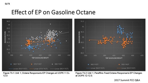
RVP and endpoint both have a minor effect on gasoline octane. With other operating parameter changes and repeatability of octane results in the lab (+/- 0.5 RON), it is difficult to quantify small changes in octane caused by fractionation changes. Literature suggests that for every 1.5 psi RVP increase, RON will increase 0.3. We have very little data to support the literature, because the octane and RVP value of mixed C4s is much greater as alkylate than on the frontend of FCC gasoline. The effect of gasoline EP on octane depends on feedstock quality. For hydrogen deficient feedstocks, an increase in gasoline EP will increase RON. This relationship is shown in Figure 73-1, which represents operating data from Unit 1 at 22 to 24 API Gravity, UOPK 11 to 12, and 0.12 to 0.15 wt% sulfur. Figure 73-1 suggests a one-number increase in RON for every 50-degree change in EP.
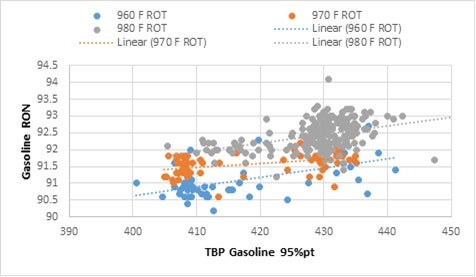
Figure 73-1. Unit 1 Octane Response to EP at Various Riser Outlet Temperatures (ROTs) for Feed Qualities of 22-24 API Gravity and 0.12 to 0.15 wt% sulfur
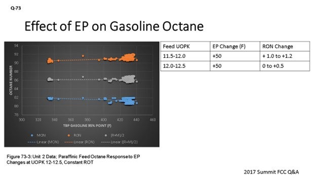
However, as feedstock and products become more paraffinic, the octane response to EP is less dramatic. This relationship is shown in the operating data shown in Figures 73-2 (Unit 1) and 73-3 (Unit 2). Both units are operating with a paraffinic feedstock. In Figure 73-2, the same Unit 1 under conditions where the UOPK is 12 to 12.5, API Gravity 26 to 29 showed a decreasing response in octane with EP. Data from Unit 2 (Figure 73-3), also with a paraffinic feedstock, suggests that a 50-degree change in EP will increase RON by 0.5. This figure also shows that MON is flat or decreasing, resulting in a flat R+M/2 result.
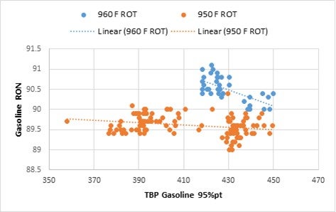
Figure 73-2. Unit 1 Octane Response to EP at Various Riser Outlet Temperatures for Feed Qualities of 26-29 API Gravity and 0.005 to 0.02 wt% Sulfur
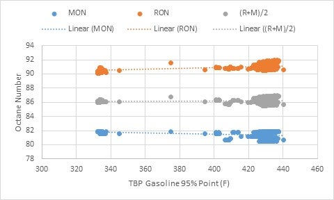
Figure 73-3. Unit 3 Octane Response to EP at Various Riser Outlet Temperatures for Feed Qualities of 26-29 API Gravity and 0.005 to 0.02 wt% Sulfur
SANJAY BHARGAVA (KBC Advanced Technologies)
Refineries use multiple configurations to split FCC gasoline into a high-octane LCCN and low-octane HCCN. The split can be made either in the main fractionator with HCCN side-draw or in a naphtha splitter downstream of the debutanizer. A detailed, nonlinear, blender model with a representative fractionation model should be used to optimize the cutpoint and fractionation between LCCN and HCCN in situations where the gasoline blender is hitting multiple constraints, such as octane, aromatics, and olefins. This flexibility results in more profitable gasoline blends.
Some refiners have an additional MCCN (medium catalytic-cracked naphtha) cut which has a still lower octane and which gets post-treated in a reformer to increase the octane of the MCCN. Removing the low-octane MCCN from LCCN and HCCN increases the octane of the remaining LCCN and HCCN.
In general, the octane response with endpoint change is very flat and hard to detect in the plant due to the repeatability and reproducibility of RONC/MONC (research octane number clear/motor octane number clear) being higher than any predicted theoretical change. Theoretically, higher octane is attained as endpoint rises but then drops on further increases in endpoint.
Hence, we have no rules of thumb between octane and endpoint of gasoline as the octane profile changes more due to other FCC variables, such as feed quality, severity of operation, catalyst, use of ZSM-5, and fractionation efficiency. Further, the octane profile can also change over the course of operation as the fractionator fouls due to salt deposition in the top of the tower.
Question 74: How do you mitigate aqueous corrosion in the main fractionator overhead and gas concentration unit? What contaminants do you test for in the sour water, and what limits do you impose? What are your concerns with using stripped sour water as waterwash?
DINKEL [Marathon Petroleum Corporation (MPC)]
There are quite a few questions from previous Q&As and Cat Cracker meetings, so I will summarize them in the written response in the Answer Book section of the final transcript.
I will stress that design details are important to make sure the injection quill is designed right with the correct lengths of pipe run, as well as to confirm that your sour water handling is set up appropriately.
The commercial example I will discuss is about one of our units that, years ago, needed to increase the washwater rate to the main column overhead. We define the washwater requirement by doing ionic modeling and then setting the target with a 15°F buffer above the dew point. The required water rates would have required an overhaul of the entire overhead system, including the waterdraws, boots, pumps, and piping. Their solution was to put a staged injection into the fin fans in the overhead system. The system consists of automated valves and a PLC (programmable logic controller) that controls and sequencing through the fans. It is injecting for a set period of time on each fan bank. It goes down the line and then comes back to the front of the line. That is a way to mitigate really having to increase the amounts of sour water handling on the unit.
I will share a good example about the importance of getting the design details correct based on inspection findings during the last turnaround. We inspected those fin fans and discovered that about half of them had accelerated wall loss, which meant that there was accelerated corrosion of the tubes. The investigation aligned the different corrosion rates with a hydraulic piping difference. There was a smaller diameter piping on the wash water to the specific exchangers with higher corrosion. They were added on at a later time, and the new piping was a different thickness than the original piping. It ended up being about a 20% lower washwater rate to those fin fans; so, it is just very important to pay attention to the design details.
Regarding the part of the question about whether or not stripped sour water is used, I will tell you that we do not use stripped sour water to overhead in any of our units. However, I do not see why you could not, as long as you are monitoring your sour water containments, purging the system, and making up with a clean water source appropriately.
The next slide is about the gas concentration system. I will just highlight that the objective for us is to remove the water, and our preferred option is using the coalescer. We have had good success with being able to remove the water with a coalescer on the stripper feed, and we were able to dry up the debutanizer. You do not see any moisture in that overhead system, and there is the added benefit of it being energy efficient. You also end up debottlenecking that tower, so you will be reducing the loading and getting some performance benefit.
BHARGAVA (KBC Advanced Technologies, Inc.)
I want to add to what Bryan said about aqueous corrosion. The aqueous corrosion is best handled by injecting water before the fin fans and the overhead of the fractionator. Inside the fractionator, you have three deposits, including ammonium chloride. And if you have those deposits, you will not want to leave it there because you will underdeposit corrosion.
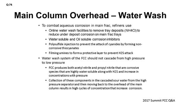
You have waterwash facilities you have seen where your clients have – on a regular basis – water-soluble and oil-soluble corrosion inhibitors, polysulfide injection to prevent the attack of cyanides by forming non-corrosive thiocyanates, and filming as means of forming a protective layer to prevent H2S (hydrogen sulfide). These are all different mechanisms that can be used to reduce the corrosion in the overhead system.
Finally, we prefer a parallel wash system to protect upstream and downstream of the wet gas compressor. If it loads the sour water stripper too much, the second option is to go over the coker and waterwash system. The countercurrent is not preferred because it creates a recycle of the cyanides from the high-pressure area to the low-pressure system.
TRAGESSER (KBR)
Corrosion in FCC main fractionators can be broken down into mainly corrosion of steel by sulfides and cyanides and hydrogen blistering. Water, ammonia, and H2S – along with trace number of chlorides – are present in fractionator overhead systems. Corrosion is typically higher for units processing heavier feedstocks with high amount of sulfur and nitrogen in the feed.
Hydrogen blistering is found to be the most common concern in FCC recovery units. However, the prevention begins at main fractionator. KBR provides waterwash in the fractionator overhead system to dilute cyanides, prevent salts from building up, and control pH. We use water collected from wet gas compressor interstage drum, high pressure separator drum as wash water. In our experience, injection of this water minimizes the possibility of salt deposition on the tube surface of the exchanger. The relatively high wash water pH also helps dissolve acidic polysulfides into the water phase. Net wash water, along with the water condensed from the fractionator overhead, is rejected in the fractionator reflux drum and sent to the sour water stripper. KBR also recommends using a corrosion inhibitor in the main fractionator overhead system to prevent hydrogen blistering in the downstream section. Typically, ammonium polysulphate solution is used as corrosion inhibitor.
To further minimize the possibility of hydrogen blistering in the vapor recovery unit, we use wash water injection at both hot discharges of the wet gas compressor. The water dissolves components in the gas stream that would otherwise promote hydrogen blistering. Corrosive soluble salts are also removed by waterwashing as well. As a side benefit, the water injection also provides some cooling of the compressor discharge streams. Usually, oxygen-free steam condensate is used as the source of the wash water. Oxygen brought in with wash water can create severe corrosion.
We believe that non-phenolic stripped sour water can be used as the waterwash in the FCC. However, care must be taken as sour water from the FCC sour water stripper would usually have residual phenolic compounds. Therefore, sour water from FCC sour water stripper should be avoided.
BRYAN DINKEL [Marathon Petroleum Corporation (MPC)]
Over the last six years, there have been a number of questions related to different aspects of overhead and gas concentration unit corrosion management, including design recommendations. For completion of the Answer Book, here is a brief summary of the topics covered. Please refer to the following historical transcripts and/or Answer Books for full details:
-
2016 Q&A, Question 65: Feed property impacts, the use of chemicals for corrosion control, and whether or not waterwash is a sufficient strategy when used on its own
-
2014 Q&A, Question 95: Design of wash water nozzles
-
2014 Cat Cracker, Question 11: Recommendations for waterwash rates and locations and sources of makeup
-
2012 Cat Cracker, Question 33: Techniques for and frequency of collection of sour water samples and the specific contaminants monitored
-
2011 Q&A, Question 79: Management of chloride fouling in FCC fractionators
As discussed in these previous-year responses, MPC also uses ionic modeling to determine the salt dew point. Our internal recommendation is to set a minimum tower top temperature 15°F above the dew point. In the tower, corrosion is avoided by using a spray header reflux distributor and by limiting the minimum reflux temperature to approximately 210°F. The spray distributor allows for direct contact heat transfer prior to the top of the packed bed, which helps to avoid shock condensation.
The design details of the main column overhead waterwash injection systems are important. Some of the components that need to be reviewed carefully include the design of injection quills, recommended upstream/downstream pipe runs, piping hydraulics for the balanced flow to parallel exchangers in continuous waterwash systems, and water disposal limitations. Regarding sour water handling limitations, one option to address is a major redesign of water handling and disposal components: water boots, pumps, piping, and control valves. An alternate solution we have implemented on one of our units is batch injection of water to individual overhead fin fans, which also reduces the duty load on the downstream condensers. This staged injection of water is automated such that it cycles between the multiple fin fans, injecting water for a set period of time on each and then starting back at the beginning.
An example highlighting the need to review design details stems from these fin fans on the staged waterwash sequence. During turnaround, inspection of the fin fan tubes identified some exchangers with accelerated wall loss compared to the remainder of the fan banks. Upon investigation, it was identified that the accelerated corrosion was on exchangers with smaller wash water supply piping and a lower flow rate of filmer due to the injection point locations. For the waterwash rates alone, the piping difference resulted in about 20% lower wash water which contributed to the accelerated corrosion.
I have no direct experience with using stripped sour water as a makeup water source; however, one should be able to use it as long as contaminant levels are monitored to determine if they are cycling up over time. Ideally, a purge and fresh, clean makeup water source should be utilized to control contaminant loading. I am familiar with the use of condensate as a clean source to supplement the quantity of steam feeding forward to the fractionator from the reactor.
Regarding corrosion control in the gas concentration unit, MPC’s preference is to remove the water from the absorber and stripper feed to eliminate the water source throughout the gas concentration unit for both corrosion control and debottlenecking the stripper tower loading. Water removal can be accomplished with the use of a water trap-out tray or feed coalescers or by preheating the feed to the stripper and recycling that feed back to the high-pressure separator for another pass at removing the water. MPC has implemented each solution. Our preference is the coalescing option based on water removal performance; it is a more energy-efficient solution. We have one unit with a coalescer on the stripper feed which has resulted in maintaining the debutanizer overhead system dry.
SANJAY BHARGAVA (KBC Advanced Technologies)
In FCCs, we have general and localized aqueous corrosion due to water-soluble corrosive species; typically, H2S and hydrogen cyanide. The FCC systems also have ammonium chloride salts that deposit on the main fractionator trays and overhead prior to water injection in the overhead; thus, it is common to have wet underdeposit corrosion mechanisms. Refiners have waterwash facilities to remove the ammonium chloride from the main fractionator intermittently. Refiners also have both water-soluble and oil-soluble inhibitors as part of the corrosion control program.
Any freshwater makeup should be either condensate, BFW (boiler feed water), or stripped sour water of the correct quality. Polysulfide injection can prevent the attack of cyanides by forming non-corrosive thiocyanates. Filming amines have also been used to form a protective layer to prevent H2S attack.
The waterwash system of the FCC should not cascade from high pressure to low pressure. The FCC produces both acetyl nitrile and propyl nitrile which are corrosive species that are highly water-soluble, along with H2S, and increase in concentration with pressure. The collection of these components in the cascaded sour water from the high-pressure separator and then moving the water back to the overhead of the main column results in high cycles of concentration that increase corrosion.
The sour water should be tested for Fe, NH3 (ammonia), and chlorides.
Properly controlled sour water stripper can provide a good source of reuse water in the FCC overhead. The contained ammonia can actually assist in corrosion control in the overhead system. This practice has been done without issue but should be reviewed for a specific application at a site.
CHRIS CLAESEN (Nalco Champion)
Corrosion and fouling mechanisms are mainly governed by HCl, NH4Cl (ammonium chloride), NH4HS (ammonium hydrosulfide), and cyanide contents or formation temperatures. A good waterwash helps to control the overhead corrosion, but problems may also exist in the fractionator top. This issue can only be controlled by reducing HCl levels or by implementing a salt dispersant. Pathfinder ionic modelling will determine the formation temperatures of NH4Cl and NH4HS and help determine the actions needed to control this situation. Cyanide levels can be controlled with the use of APS. Stripped sour water is a good source for a waterwash as long as it does not introduce oxygen, hardness, corrosives, or foulants.
Question 75: What are your Best Practices in design and operation to achieve positive isolation of slurry/HCO equipment?
DINKEL [Marathon Petroleum Corporation (MPC)]
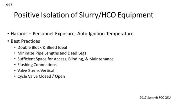
The hazards of your slurry and HCO system include the fact that you get hot oil operating close to auto-ignition temperatures. If it is released, there is a risk of it lighting off, as well as the risk of exposure to personnel. The crux of the question is really around maintaining or confirming positive isolation so you can access the equipment and conduct maintenance activities.
Some Best Practices: If you had a clean sheet of paper, you would do double-block-and-bleed; however, most units do not have that configuration. That design would not have been installed years ago. It is very congested underneath the main fractionator and rather expensive to go in and retrofit the slurry circuit with additional valves. So, if you have the opportunity and are already making some piping modifications, you should minimize pipe lengths and get rid of dead legs in that system that would allow areas for solids to accumulate. You will also need to be cognizant that you have sufficient space in there to provide access for the Maintenance workers to come in, do their job, and have a good regress from the area.
You want to have flushing connections to valves, as well as piping. For valves, the connection should be right on the seat, in case you get solids buildup in the seat. You should also have connections that can be hooked up with LCO to try to clear plugging. We like to try to have the valve stems in the vertical position because they keep solids from potentially accumulating up around the bonnet area.
My last point is from an operational standpoint. If the valve is not holding, the field operators will cycle it open and closed to vary the velocity across the seat of the valve and try to sweep out any solids that will have accumulated.
DARIN FOOTE (CHS Inc.)
The following are some important principles of design and operation that will help ensure positive isolation of heavy oil circuits in the FCCU main fractionator system.
Principles of Design
-
Proper Line Sizing: Maintaining an operating velocity of 4 to 10 fps is important for circuits on the discharge side of pumps. On the suction side of pumps, a velocity of 3 to 5 fps is desired. Keeping the velocity elevated will help prevent slurry deposits in valve seats.
-
Double Isolation: Where geometries allow, consider double block and bleed connections and make provisions for blinding.
-
Minimize Dead Legs: Locate the isolation valves for pumps as close to the continuously flowing line as practicable, preferably fitting makeup if stress allows. Also avoid geometries that are prone to catalyst settling out.
-
Flush Connections: Make provisions for flush connections on the bottom of the line – on both sides of equipment that is routinely isolated – within the block valves. Ensure that these connections can be cleaned with a straight bleeder cleaner.
-
Valve Selection:
-
Gate valves are the most robust and common in this service. 5Cr-0.5 Mo with API Trim #8 with the stem mounted in the horizontal where possible. There is no complex mechanism, and you can beat on the seat and stem to get them to seal.
-
Flush-Ported Gate Valves: Some have used these with mixed success.
-
Triple-Offset High-Performance Butterfly Valves: We have one of these in service as an emergency isolation valve from the main column to the slurry pumps. We have never had to use it, nor have we made a complete run with it yet. On our next shutdown, we plan to test this valve.
-
Wedge Plug Valves: These have a proven track record in slurry and coker service. The design ensures that the seat remains clear. Some designs, however, require steam purge; so, be cautious if using them in pump suction applications. These valves usually must be sent off for repair since most sites do not have the expertise to work on them. If the timing mechanism is not set properly, the valve will not seat.
Principles of Operation:
-
Exercise the valve as you close it. Open and close against the seat multiple times as you are isolating equipment. This action allows the seat to be exposed to higher velocities just before closing off. In cases of pump suction and discharge where this is not possible, utilize pump seal flush and/or other flush connections to generate flow across the seat.
-
Monitor isolation while steaming. There have been incidents in our industry where initial isolation was thought to be complete. After steaming the circuit, the catalyst in the seat of the valve breaks free and causes a loss of containment.
-
Monitor steaming operations and watch for signs of valve leakage.
-
Ensure that hoses used are rated for process temperature and that the location where condensate is routed has been evaluated for the potential of process leaking back into the system.
ALEX MALLER (TechnipFMC Process Technology)
Technip’s practice is to specify gate valves with flushing connections at the base of the seat. To ensure positive isolation, the flushing connection can be used to remove any sediments that may be impact the contact of the gate with the seat. Another option is to orient the valve stem off of vertical in order to move the final seating location away from the low point, therefore reducing the chances of sediment to accumulate there. This type of valve orientation is only possible given that space is available. Most importantly, these valves should be overhauled during every turnaround to ensure their long-term reliability.
BRYAN DINKEL [Marathon Petroleum Corporation (MPC)]
Positive isolation of slurry and heavy cycle oil (HCO) equipment is important in order to prepare equipment for maintenance activities or to isolate hydrocarbon source in the event of loss of containment. Risks include fire and personnel exposure to hot process materials. Across a typical slurry pumparound circuit, operating temperatures will range from as high as about 690°F at the tower bottoms down to about 550°F return temperature. Apart from hydrocarbon flammability, slurry has the added potential to operate near the auto-ignition temperature (AIT); the pumps are at highest risk due to the slurry being at its hottest temperature directly off the tower. The AIT of slurry is approximately 750°F and of HCO is approximately 500°F. Slurry contains a mixture of catalyst fines and coke, which both lead to a higher risk of an obstruction that could inhibit isolation and verification steps.
The ideal installation includes double-block-and-bleeds with sufficient straight runs of piping for access, blinding, and maintenance while also working to minimize the distance between the tower bottoms and pumps. Minimize the presence of dead legs within the circuit that provide a location for solids to settle out. Block valves should have the stems in the vertical position – or as close to vertical as possible – to minimize the risk of catalyst collecting in the valve bonnet. In reality, most units were not originally designed with a double-blocks valve configuration and will have single-block valves. The cost of a retrofit is not trivial, particularly when there are options available to clear the seat of a valve of deposits. Flushing oil connections to the valve allows for the direct addition of flushing oil to the valve seat. The cycling of the valve opened and closed to dislodge any deposits that settled in the seat of the valve is also an effective Operations trick. For verification of positive isolation, bleeders are used; or in scenarios when bleeders are not available, bleeder blinds can be installed.