Question 47: For units not challenged by standpipe fluidization, are there benefits to reducing fresh catalyst 0-40 um particle content?
TODD HOCHHEISER (Johnson Matthey)
There are multiple benefits to reducing fresh catalyst 0–40-micron particle content for FCCs not challenged by fluidization. A significant portion of the 0-40 content cannot be retained in the FCC. Therefore, reducing the 0-40 content will result in less fresh catalyst being lost shortly after being added.
Lowering fresh catalyst losses has numerous advantages. Fresh catalyst addition rate and therefore fresh catalyst expense will be lower. On the reactor side, lower losses can result in lower slurry ash content, improved heat transfer in the slurry circuit, and reduced slurry heat exchanger and slurry tank cleaning frequency. For units with slurry filtration systems, lowering fresh catalyst 0-40 content will reduce particulate load. On the regenerator side, there will be less fines generated for disposal. If the FCC has a wet gas scrubber, the scrubber purge will contain less solids reducing the impact to the purge treatment and wastewater treatment units.
Stack particulate matter can also be reduced when shifting to a lower 0-40. Most of the fresh catalyst 0-40 content leaving the regenerator should be captured by the ESP or third stage separator. For units with underperforming ESPs or third stage separators, the 0-40 content reduction could have a noticeable impact on particulate matter compliance. The opacity reduction is not expected to be as large as the particulate matter reduction since opacity is preferentially impacted by microfines.
There are cases where shifting to a coarser particle size distribution has helped turboexpander performance. The fines lost directly from the fresh catalyst had a larger average particle size. In these cases, the coarser fines helped to clean the deposition of microfines on the turboexpander blades. This benefit strongly depends on the performance of the third stage separator.
In order to make the shift to a lower 0-40 content, the entire particle size distribution can be shifted in the coarser direction. This is accomplished by adjusting atomization in the spray drying process. It is recommended to speak with your catalyst supplier regarding their ability to shift spray dryer operation and the impact it may have on other catalyst properties. Another way to reduce to a lower 0-40 content is through classifying. Classifying to remove small particles is usually accomplished by wind sifting. Classifying will add to the fresh catalyst expense. The fresh catalyst expense when classifying includes standard production costs plus the cost of classifying along with disposal or reprocessing of the fines. Reducing 0-40 content through classification produces a cleaner cut compared to making the reduction during spray drying. Classifying effectively removes the front end of the distribution curve rather than shifting the particle size distribution curve.
Although the benefits discussed can be realized, for some FCCs the magnitude of the benefits will not be significant. For these units, maintaining 0-40 content can provide protection if unplanned FCC incidents occur. A cyclone hole, refractory or coke spall, or slide valve operational issues are just some of the challenges that unexpectedly arise and at that time the 0-40 content may be needed.
ZHEN FAN (Norton Engineering Consultants, Inc.)
If not fluidization limited, reducing in fresh catalyst 0–40-micron content will result in reduced losses from both the reactor and the regenerator. Of course, the attrition rate of the fresh catalyst will also contribute to the 0–40-micron fraction of the circulating inventory and may mask any improvement in losses seen by dropping the fresh catalyst 0-40 content.
MICHAEL FEDERSPIEL (W. R. Grace & Co.)
Typically, FCC catalyst is manufactured such that the particle size distribution of the fresh catalyst is within the range most suitable to circulate in a wide variety of FCC units.
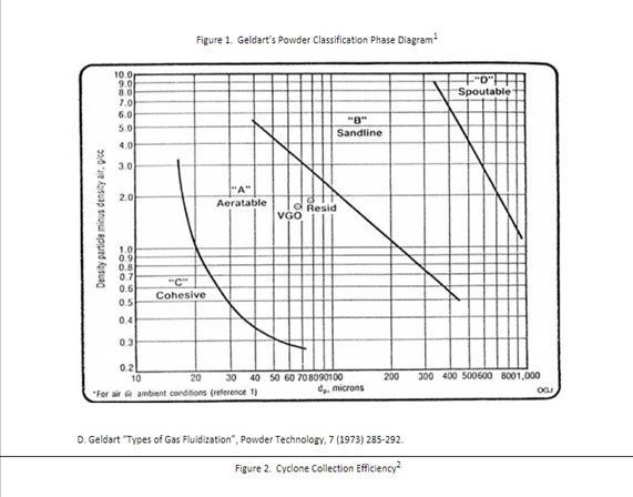
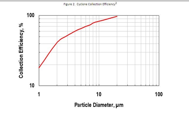
The average particle size is typically manufactured to be in the middle of the Geldart’s “Aeratable” zone (see figure 1) and the smallest particles (0 to 20 µm) are minimized due to FCC cyclones inherent inability to retain those particles (see figure 2).
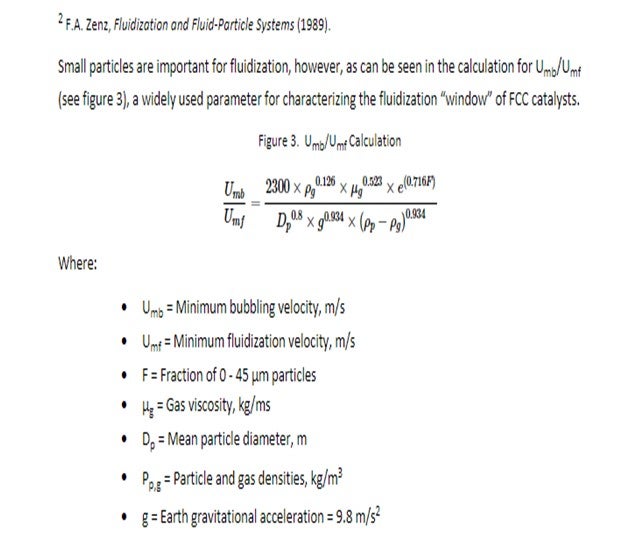
Small particles are important for fluidization, however, as can be seen in the calculation for Umb/Umf (see figure 3), a widely used parameter for characterizing the fluidization “window” of FCC catalysts.
From the equation above, we note that 0 to 45 µm catalyst plays a role in improving the fluidization window. These small particles serve to fill the voids between larger particles and slow down de-aeration of gas from the catalyst.
Maintaining catalyst fluidization at all times is critical to FCC operation. In addition to the health of the catalyst; the unit operations, and the mechanical design and condition of the equipment will all play a role in catalyst fluidization.
If there are no concerns regarding the fluidization of the catalyst in the unit, there may be some benefits to reducing the amount of the smallest particles in the fresh catalyst.
Reducing fresh catalyst 0 to 40 µm material can help reduce stack opacity. The smallest particles have the biggest impact on opacity, as they are closest to the wavelength of the light projected during the opacity measurement, are typically not retained by the cyclones. While fines are generated during the normal circulation of FCC catalyst, reducing the amount coming in with the fresh catalyst can help reduce stack opacity.
If a refinery has developed a hole in their cyclones, and since they are no longer able to retain the small particles in the unit, reducing fresh catalyst fines content can reduce the amount of material passed to either the slurry or scrubber/ESP. This can improve product quality of the slurry oil or reduce waste material handling from the regenerator side. If the refinery has a power recovery expander, this could also help reduce erosion on the turbine.
Grace offers some flexibility in our fresh catalyst formulations to help those refiners who could benefit from reducing fresh catalyst 0 to 40 µm content. Additionally, there are companies that offer catalyst classification and screening. It’s important to work with your supplier to make sure you understand the potential risk and benefits of reducing fresh catalyst 0-40 µm particle content.
Year
2019
Submitter
Process
Question 48: What is your experience with carbon on regenerated catalyst levels in partial burn operations? How do you confirm an optimal level of carbon to ensure desired product yields? How do metal amounts or feedstock play a role in controlling carbon on regenerated catalyst?
TODD HOCHHEISER (Johnson Matthey)
The optimal level of carbon on regenerated catalyst (CRC) is often a balance between conversion and feed rate. Lowering CRC can be achieved by increasing air rate. In FCCs that are air blower or regenerator temperature limited, this can result in a feed rate reduction or residue processing reduction. The benefit of operating at the lower CRC is increased ecat activity and conversion.
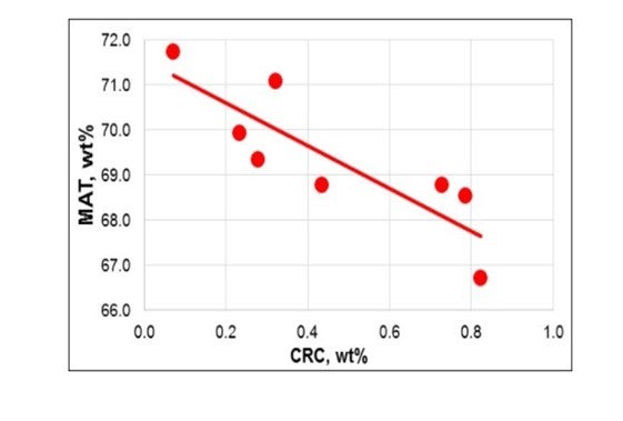
The JM laboratory conducted an expert with a spent catalyst sample. The spent catalyst contained 1.2 wt% carbon and was taken from a two stage FCC unit processing residue feed. The sample was divided, and the coke was burned off to varying levels ranging from 0.07 wt% to 0.82 wt%. Each sample was then processed on a ACE unit. MAT decreased by 1 wt% for each 0.2 wt% increase in CRC (see Figure). The activity loss slope will be specific to the FCC, catalyst type, and ACE testing protocol.
Another method to evaluate the impact of CRC on activity is based on routine ecat testing. Ecat activity results are usually reported after calcining the sample. ACE testing can also be conducted on the sample prior to calcining. The activity gain from calcining shows the impact CRC has on that particular sample. A trend can be developed by plotting the activity delta from calcining versus CRC.
When operating at higher CRC, delta coke is reduced. For units that are delta coke limited, the right balance needs to be found between CRC and delta coke. If feed metals are increased, delta coke will increase. One method to combat the higher metals is to raise CRC thereby lowering delta coke. In this scenario, the higher metals will impact conversion negatively for two reasons: ecat metals poisoning and operating at higher CRC.
Catalyst formulation can be evaluated to switch to a lower delta coke catalyst. This will allow lower CRC while still staying within regenerator temperature limits. Metal trapping additives can also be used to reduce delta coke.
DAVID HUNT (W. R. Grace & Co.)
FCCU partial combustion operation brings additional operating complexity relative to a full combustion regenerator operation. Before equilibrium catalyst activity is measured by the catalyst supplier, coke is traditionally burned clean, and the activity is reported on a carbon free basis. For operations where carbon on regenerator catalyst is greater than ~ 0.25 wt.% the effective in unit equilibrium catalyst activity may be less than the reported value.
Excessive carbon level can be a process safety risk in addition to producing high slurry oil and lower conversion. Carbon will generally cover the most active sites enriched with the youngest catalyst fraction.
The amount of carbon on the regenerated catalyst is influenced by several factors including the following:
- Feedstock and recycle rates
- Feedstock properties (Conradson carbon)
- Regenerator combustion air rate
- Flue gas carbon monoxide (CO)
- Regenerator temperature
- Regenerator and riser residence time
- Catalyst activity
- Metals
- CO combustion activity
- Additives
- Particle Size Distribution
Excessive carbon on regenerated catalyst is often a challenge for constrained units operating a partial combustion regenerator at increased feed rates with heavier feedstocks.
When feedstock Conradson carbon levels increase additional coke is deposited onto the catalyst in the riser. Since the regenerator operates with no excess oxygen, the incremental coke on catalyst increases CO levels and finally carbon on regenerated catalyst for the same combustion air rate. Slurry recycle produces an even more dramatic effect due to the relatively high Conradson carbon level.
Dehydrogenation metals such as nickel and vanadium behave in a similar fashion as Conradson carbon. In the riser delta coke on catalyst increases with these metals moving the regenerator into a deeper partial burn with higher carbon on regenerated catalyst at fixed operating conditions.
Excessive CO combustion activity can strongly drive the C + O2 > CO2 combustion reaction versus C + 1/2O2 > CO consuming more oxygen relative to carbon increasing carbon levels on the catalyst.
Increased average particle size has been linked to higher carbon on regenerated catalyst. Increased regenerator bubble size and less mass transfer to the emulsion was suspected. (1)
Slow combustion kinetics at low regenerator temperature have caused high carbon levels. (1)
Grace is also aware of instances where high levels of “hard coke” are observed on regenerated catalyst where traditional regenerator temperatures are unable to burn the catalyst clean. Several factors are believed to be at play. Grace has worked closely with our customers in those instances to optimize the unit and bring carbon levels back to acceptable levels.
Generally lower catalyst activity and an increased amount of metal trapping are required to reduce delta coke and maintain optimal levels of carbon on regenerated catalyst in a constrained partial combustion regenerator operation with residual feedstocks. Working with your catalyst supplier to continuously optimize the catalyst and partial combustion operation is highly recommended to ensure a profitable and safe operation.
- Indian Refiner Presents Troubleshooting Examples for a Partial Combustion FCC Regenerator, Das et al, Oil and Gas Journal, Sept 4, 2000
CHRIS STEVES (Norton Engineering Consultants, Inc.)
The catalyst and air distribution in a partial burn FCC regenerator will have an impact on the carbon on regenerated catalyst, as well as the operation (primarily regenerator temperatures). The impact on yields for different CRC levels will depend on the feed quality and the catalyst type and should be evaluated through unit testing and trending of historical information, taking care to compare periods with similar feed types and catalyst types.
Year
2019
Process
Question 50: What methods or operating parameters do you use to monitor/diagnose FCCU regenerator air and catalyst maldistribution? What can be done operationally to mitigate air and catalyst maldistribution? What mechanical changes have been successful at improving air and catalyst distribution?
DAVID HUNT (W. R. Grace & Co.)
Maldistribution of air and/or spent catalyst can be diagnosed by several different symptoms.
Localized regenerator afterburn is a common symptom of non-optimal air and/or spent catalyst distribution. Regional CO bed breakthrough will combust and afterburn in the regenerator dilute phase and cyclones indicating a stochiometric imbalance of air and coke. In a partial combustion operation, localized afterburn confirms confined oxygen breakthrough from the bed resulting in CO combustion in the dilute phase and cyclones. The use of combustion promoter in either operation (full or partial combustion) is commonly used to reduce afterburn for FCCU’s with non-ideal air and spent catalyst distribution.
Excessive catalyst losses are another symptom of poor air distribution resulting in localized high catalyst entrainment exceeding the capacity of the cyclones in that region of the regenerator. High velocity from a partially plugged distributor could also increase catalyst attrition producing higher catalyst losses.
Poor air distribution may also result in zones of de-fluidized catalysts within in the regenerator. High catalyst losses maybe observed due to cyclone diplegs attempting to discharge into the de-fluidized zone resulting in dipleg backup. If the regenerated catalyst enters the standpipe from any zone of de-fluidized catalyst, poor pressure builds in the standpipe maybe observed reducing unit catalyst circulation capacity or stability.
A change in air or spent catalyst distribution may also be identified by a shift in temperatures within the bed, dilute phase or cyclone outlet. Ideally these temperatures will all be similar, say within +/- 10°F. If the temperature difference increases suddenly, over time or across a shutdown then a deterioration of air or spent catalyst distribution may have occurred. Or in similar fashion if the cyclone with the historical “hottest” outlet temperature reduces and another cyclone moves to the “hottest” position then the refinery might suspect an air or spent catalyst distribution change.
Dark catalyst particles observed when the regenerated catalyst has a “salt and pepper” appearance is also a confirmation of non-ideal spent catalyst distribution and/or air maldistribution. An experienced operator “eye” is valuable in this instance.
Refiners should monitor air distributor differential pressure (dP) and compare against the expected dP calculated from the distributor design and operating conditions. Lower than expected air distributor dP suggests damage such as a hole, worn restriction orifices or distributor-arm separation from the header. Higher than expected dP could mean a partially plugged distributor. Both issues can result in non-optimal air distribution.
The air distributor minimum dP should be maintained within licensor requirements. Minimum dP is generally maintained within a fraction of the catalyst bed differential pressure or height. Higher bed heights will require additional distributor dP to assure air distribution across the bed and to avoid catalyst ingress within the air distributor. Downward pointed distributor nozzles may require less dP relative to upward pointed nozzles. In general, a minimum dP of 1.0 psi is adequate for most circumstances.
It’s difficult to significantly alter the air and spent catalyst distribution while operating. If poor air or spent catalyst distribution is resulting in afterburning or high catalyst losses which are constraining the unit, the operator may consider the following:
-
Use of a combustion promoter: semi-continuous injection of promoter or premixing with fresh catalyst is often more beneficial than of one or two daily injections
-
Air placement optimization for regenerator designs with multiple air rings or air distributors
-
Bed level optimization to minimize afterburn (generally higher bed height) or catalyst losses (generally lower bed height)
-
Use of supplemental O2 to reduce catalyst entrainment and losses
-
Higher regenerator pressure to reduce catalyst entrainment and improve combustion kinetics
Non-ideal spent catalyst distribution remains a challenge in today’s FCCU’s despite continuous technology advancement over the last 75 years. Surprisingly, regenerators with symmetric spent catalyst distribution and robust air distributor designs in good mechanical condition can observe afterburn suggesting non-ideal air and spent catalyst distribution.
Computational Fluid Dynamic (CFD) modeling is a useful tool to confirm spent catalyst distribution for a given design and evaluate design options. (1) Optimized delivery of the catalyst to the spent catalyst distributor can also be evaluated by CFD. Licensors offer these services as part of their study and design work as well as other consulting firms.
Finally, gamma scans and radiotracer evaluations are useful studies to confirm air and/or spent catalyst distribution and provide a justification to make planned repairs or modifications during an upcoming turnaround or unit shutdown. (2)
-
Simulation as a Tool for Learning from Historical FCCU Operations, Sam Clark, AFPM Cat Cracker Meeting, 2018, Houston TX, CAT 18-980
-
FCC Regenerator Catalyst Loss Case Study, William Mixon (Tracerco), Nicolas Larsen (Marathon Petroleum Corporation), APFM Cat Cracker Meeting, 2018, Houston TX, CAT 18-653
CHRIS STEVES and ZHEN FAN (Norton Engineering Consultants, Inc.)
Looking at the afterburn (if in full burn operation) and the distribution of that afterburn at each cyclone is the primary way to evaluate the regenerator air/catalyst distribution. Cyclones with a high afterburn are probably coke rich/air deficient and CO gas from the regenerator bed is mixing with excess O2 from an oxygen rich section of the bed and causing a high afterburn. Poor air/catalyst distribution can either be a result of the design of the unit, or mechanical damage to the air grid/ring or catalyst distribution system that should be repaired during the next available turnaround.
The distribution of air from the air ring may be impacted by bed level in the regenerator, and adjustments to the bed level can be used to evaluate the impact on afterburn. Of course, running with a higher regenerator bed level may impact catalyst losses and needs to be balanced against any potential improvement in air distribution and afterburn.
Year
2019
Process
Concurrent Subgroup Meetings
-
Hazard ID and Practice Sharing
-
Industry Learning and Outreach
-
Human Reliability Subgroup
-
Walk the Line
-
Mechanical Integrity Subgroup
-
Process Safety Site Assessments
-
Regional Network Chairs Subgroup
Session Start End
-
Industry Learning and Outreach Subgroup
Session Start End
-
Walk the Line Subgroup
Session Start End
-
Regional Networks Chairs Subgroup
Session Start End
-