Benjamin Stromberg
Sandia National Laboratories
FRY (Delek Refining)
With regard to reforming economics, the key criterion to determine catalyst condition is the surface area. As the surface area decreases, you will see yield loss on your unit, and you will have to raise the temperature in order to compensate for the lower surface area. Raising the temperature results in more cracking; so you will want to monitor the surface area. You will also want to monitor the volume loss across the unit, as well as monitoring your off gas rates.
There will come a point where you will save more in yield improvement by changing out the catalyst, and it will simply pay for itself. What that is will be unique to each facility.
LAMBIE (KBC Advanced Technologies, Inc.)
For semi-regeneration units, contamination, such as iron in the lead reactors, or unit upsets are more common issues. Skimming and catalyst replacement is a common practice to prevent downstream contamination. Skimming may occur every three to five years, depending on the effectiveness of the regenerations. Semi-regen units’ catalyst surface area and activity are not as much of an issue these days as reformers are typically operating at low severities.
For CCRs, catalyst surface area and activity are typically limiting. As the surface area reduces, the ability of the chloride to be retained on the catalyst reduces, thereby requiring high chloride injection rates, which can lead to increased downstream salting and fouling issues.
Other issues more common with CCR units that may lead to a changeout would be poisoning of the catalyst from, say, silicon contained in coker naphtha or arsenic. Poor regenerator operation can lead to sintering of the catalyst. Increased fines production in the CCR can also lead to issues, but you have the ability to replace the catalyst online for CCRs.
From a cost standpoint, the cost of semi-regens versus yield improvements, in today’s scenario where people are running very low severity reformers and getting long run-lengths, is frequently not the deciding factor. Often new catalyst formulations will come out with improved yields that may warrant a change in catalyst. Similarly for CCRs, yield improvements and activity are the deciding factors. Chloride handling costs become an issue as the surface area is reduced and more frequent changeouts of the chloride guard beds are required, which results in increased costs. And again, new catalyst formulations would improve yields and stability.
PATEL (Valero Energy Corporation)
So broadly, it depends on the operating severity. Due to lower severity operations and the fact that our CCR is a kind of noncontinuous regen type of operation we had, we changed our catalyst after 13 years of service. That catalyst change occurred during a scheduled unit inspection that required removal of the catalyst. This changeout during a reactor inspection was based on an economic evaluation. We were guaranteed C5 plus yield improvement by the licensor with the new catalyst.
KEVIN PROOPS (Koch Industries, Inc.)
If you have a semi-regen reformer, pay attention to your catalyst activity because the cycle length can very drastically. I know when I worked with Daryl years ago, one of the Conoco refineries had gotten some fairly old catalyst in a semi-regen unit; and by changing to new catalyst, it went from a six-month cycle to over a two-year cycle. So you can eliminate many of the regenerations by having a more active catalyst.
SCOTT LAMBIE (KBC Advanced Technologies, Inc.)
For semi-regenerative reformers, catalyst life is often dependent on contamination or upset-related issues. Lead reactors can become contaminated with iron, which ultimately affects the product yields. Skimming or possible replacement to prevent downstream contamination is a common practice. Depending on the regeneration procedures used, skimming may take place every three to five years.
Surface area reduction of the catalyst does not typically affect the yield loss across the unit. In extreme cases, surface area may be low and the catalyst activity affected. In some cases where good regenerations practices are followed, tail reactors may achieve up to a 10-year catalyst life.
Contaminants such as arsenic or silicon are permanent catalyst poisons for reformers and will have a detrimental impact on the catalyst activity if they are present in high enough quantities. These poisons should be managed in upstream hydrotreaters.
The main economic criteria for changing the catalyst are the cost and yields. In many refineries today, as a result of lower feed rates and/or lower operating severities, run-lengths are approaching two years and catalyst life is extending upwards of 10 years with only a relatively small change in yield loss. New catalyst formulations with improved yields and stability are increasingly dictating catalyst changeout decisions.
For CCR units, catalyst surface area reduction and activity loss are the main technical contributors to the decision to change the catalyst. The inability of the catalyst to retain chloride during regeneration results from the low surface area of the catalyst. Higher chloride injection rates and the resulting downstream fouling and corrosion become prohibitive to continuous operation for extended periods.
Contaminants such as arsenic or silicon will have a detrimental impact on the catalyst activity. These poisons should be managed in upstream hydrotreaters.
CCR units have more mechanical equipment and are more prone to potential failures or upsets that may affect the catalyst life than semi-regenerative reformers. Poor regenerator operation could lead to catalyst sintering or increased fines production. CCR units do have the capability to replace catalyst online which helps to maintain overall activity, but there is a cost associated for the lost catalyst. In some cases, consideration of the number of regeneration cycles weighs on the decision to change the catalyst.
Again, the main economic criteria for changing the catalyst are the cost and yields. The ability to control downstream fouling and corrosion resulting from increased chloride injection due to surface area loss may result in increased downtime and costs associated with water-washing and/or increased chloride bed changeout costs. New catalyst formulations in the market with improved yields and stability may justify a catalyst change.
PATEL (Valero Energy Corporation)
The major issues with some of those originally installed ball valves in CCR cyclic service are packing leaks. Hydrogen leaking into the atmosphere causes small packing fires. All too often, these failures cause process interruption and frequent ball valve changeouts. Repair and replacement create a situation that places personnel and others in danger. Our licensor dropped the old ball valve vendors from the approved vendor list.
There are better performing walls in the cyclic service that provide longer life and better reliability: the common failures experienced in the older design. All of those styles are minimized due to their superior design in the areas of packing seal and coating of the stem, which handles the frequent cycling. The detailed specification of these walls and approved supplier list, as well as their installation and the testing procedures, can be found in the licensor process specifications.
We changed eight of the old-design ball valves. They were replaced with the licensor-approved double-seated ball valves. Six were in hydrogen service and two in nitrogen service. The reason for the upgrade was poor MTBF (mean time before failure) due to numerous packing fires, leaks, and seating problems. Those valves were also removed from the licensor approved list.
After initial installation, we had to make few modifications. We had to install a stronger ball valve actuator. We had to change out the packing and lubrication because they were designed for the temperature that was specified in the original valve spec. We were not reaching that temperature. After addressing those issues, we have not had any incidents with the packing fire in the last two years, and the internal leak problems are also at minimum.
KEADY (Technip)
A gentleman I know was an Operations engineer at a client startup. He said that one of the units he worked on had issues with some of the original valves. There was wear and leakage after only a brief number of cycles, and the client had all sorts of trials with other valves and materials, including ceramics. Eventually, the client sorted out the problem, and then it became less of an issue. We do have a client in India who did not have problems with the ball valves on the CCR platform where this has been for 10plus years.
FRY (Delek Refining)
All I can add is that we use a metal-seated ball valve in our service, and it is generally reliable.
ALMA SCHURIG (Big West Oil)
We see some extreme cycles in the valves in our reformer, which uses a unique catalyst regen system (CycleX). One of the issues that we experienced, which has not yet been discussed, is that, in addition to the valve selection, we had some fairly severe piping stresses that were put on these valves just due to the piping configuration. We installed some expansion loops in the piping, and it helped a lot. We also went through several rounds trying different valve manufacturers and valve types. We have had best success with Argus metal-seated ball valves and good success with Everlasting metal-seated disc valves. The combination of piping modifications and improved valve selection has helped us quite a bit.
WAYNE WOODWARD (Valero)
With respect to the maintenance, a point lost on the turnaround folks is that you commonly pull all of these lock hopper valves (20, 30, or 40 of them) and have them serviced, and then they come back to the unit. The metal balls and metal seats always leak. If you ask your instrument man if the valves passed a bubble type of test, he will say, “Yes, it did.” Well, brand-new valves leak. My point is that you need to do the right leak check in the maintenance cycle on these valves. A brand-new valve fresh from the factory leaks 10% of allowable. Talk with your licensor about the leak check and its limits and understand that all metal-seated ball valves leak. You will need to do the leak check correctly to ensure that the valves only leak an acceptable amount. You also need to know that you are installing valves fit for service after you have done your turnaround.
GRAHAM NEWMAN (Emerson Process Management)
From the question, it is not clear which style of valve in cyclic service is of the highest interest. There are two types of cyclic services that are specific to the CCR process, each with different requirements and potential pitfalls. There are on/off valves in vapor service with catalyst dust, such as those that vent the lock hoppers, and the on/off valves in flowing catalyst service, such as those used for catalyst flowing in and out of the lock hoppers. The on/off valves in the dust-laden vapor flow require tight shutoff and the capability to withstand the erosive effects of flowing catalyst. Early solutions to this application used a complicated plug design which involved moving parts and springs exposed to the process fluid, which often became jammed due to catalyst buildup. This additional complexity often meant that regular maintenance could not be performed onsite for these valves; they had to be sent back to the factory. Fisher’s EZ-OVT design solved these issues by using a valve plug with no moving parts, using a dual seal and a deflector ring to keep erosive flow away from the soft sealing surface of the plug that provides the tight shutoff. This extends the operating life of the valve between service intervals. The soft components that are in contact with the process fluid are entirely replaceable, including the soft material in the plug which provides the tight shutoff. Maintenance procedures are almost identical between the EZ-OVT and the standard Fisher EZ, and the majority of the valve’s components are common to the regular EZ. This ease of maintenance and lowered parts consumption reduces these valves to a standard maintenance item at turnaround time rather than a valve that needs special attention.
The challenge for control valves in flowing catalyst service in the CCR section is to avoid damaging catalyst as much as possible when the valves close against the downward flow of catalyst. A segmented ball valve with a clearance gap between the ball and seal is specified. This clearance minimizes catalyst from being crushed between the ball and seal when the segmented ball rotates during valve closure, which would increase catalyst attrition. The segmented ball valve with clearance gap is specified for units that operate the regenerator close to atmospheric pressure. For more current designs, the regenerator operates at the fuel gas header pressure, typically around 35 psig. The same concerns about crushing catalyst apply in the pressurized units, with the additional requirement that the control valve provide bi-directional shutoff capability. For these services, a segmented ball valve with a zero-deflection seal can provide shutoff without excessively damaging catalyst during valve movement. Fisher has seen success using another variant of the Fisher Vee-Ball™ line, the SS-252B, which includes these design features. These valves are not in a high cycle service but typically only close during abnormal operation, which also minimizes catalyst damage.
GINGER KEADY (Technip)
The original UOP CCR used Hills McCanna ball valves, and there were issues with wear and leakage after only a brief number of cycles. There were trials using other valves and materials including ceramics. Eventually, the valves became less of an issue.
We have an Indian client that has had no problems with ball valves on its CCR platformer which has been in service 10+ years.
DUNHAM (UOP)
The length of the oxidation period will vary from a minimum of 11 hours up to 24 hours. The timeframe will depend on the amount of platinum agglomeration, surface area, oxygen content, and chloride injection rate. Minimizing the burn temperature during the primary burn will minimize agglomeration. So, if you are dealing with low surface area catalyst, you will need a richer chloride environment, which is a lower hydrogen-in-chloride ratio, when you are in that step.
Historically, oxygen contents were held lower. But recently, these concentrations have been going up as high as 12%. Some of the safety issues have already been addressed. Higher concentration of oxygen increases the rate of metal redispersion. When you get finished with this step, if you have catalyst samplers, you can get a sample of the catalyst. A nice creamy color tells you the oxidation step was done right.
PATEL (Valero Energy Corporation)
Unless time is critical, adding extra time could result in an advantage. Improvements have been noted in catalyst appearance when extending the oxidation period from the typical 11 to 16 hours up to 24 hours. Holding in the oxidation state for up to 36 hours could also be acceptable except that beyond that, there is a little benefit to the catalyst and there is a high risk of increased corrosion in the unit because you are still injecting a lot of chlorides and making up the caustic.
For the oxygen concentration, increasing the amount of oxygen partial pressure will speed up the rate at which the oxidation is complete. Also, a high concentration of oxygen should increase the rate of metal redispersion. Prior to increasing any oxygen concentration beyond the recommended minimum 5%, the compressor configuration should be reviewed because centrifugal recycle compressor with lube oil sealed system may hit the exploding limit with higher oxygen concentration.
CLAY MARBRY (Roddey Engineering Services, Inc.)
That was a good point about the lube oil system and potential ignition of the compressor lube oil. If you get more than 8% oxygen, you can start to see some problems there. We have also seen some coke ignite in the feed effluent exchange section. If you get above 8% oxygen, some harder-to-burn coke, such as graphitic coke, can ignite. The form of this coke can be debated; but in our experience, we have seen coke in the feed effluent exchangers ignite at higher oxygen concentrations.
An additional thought on increasing oxygen concentration: The higher the oxygen concentration you reach during the oxidation step, the longer the purge step will take to reduce the oxygen concentration to acceptable levels before hydrogen introduction in the reduction step.
As far as extending the oxidation step time is concerned, that is a fantastic maintenance hold period if you have an upset or a problem. We have been in regenerations where we have held the oxidation step for multiple days. You run the risk of corrosion, and you are using up caustic the whole time. There is a cost associated with extending the oxidation step, but this is the safest time, for the catalyst, to extend the regeneration.
DUNHAM (UOP)
Occasionally, isomerization units will slip some HCl or organic chlorides at the bottom of the stabilizer. The key here is having the proper reflux ratio on that tower because you need to keep the partial pressure of the HCl low enough that it will not overheat. So, you need a reflux-to-feed ratio of 0.5 to 0.8 to make sure that this chloride will not go down the stabilizer. We often see some refiners doing an energy audit. So, I will say, “Gee, we could save some energy if we cut the reflux ratio.” When they do the simulation, they see that it does not have the HCl. They do not understand that the HCl will go down the tower. I have seen this on a C4 isomerization unit. A customer sent a lot of chloride over to a sulfuric acid unit. The fractionator was wet, and the whole downstream overhead system was severely corroded. So, you really must be careful about stripping chloride out of the butane product.
PATEL (Valero Energy Corporation)
The HCl or organic chloride slip can occur in the isom stabilizer bottom. The reformer stabilizer operates at a relatively higher temperature, and the HCl should decompose at that condition. However, heavy organic chloride slip can occur from the reformer stabilizer bottom. Just maintaining a sufficient reflux-to-feed ratio for internal traffic in the isom stabilizer can push the HCl into the overhead where it belongs. The recommended reflux-to-feed ratio for the stabilizer is 0.5 to 0.8. However, at our unit, we operate at as low as a 0.25 reflux-to-feed ratio without experiencing any bottom slippage issues. In the reformer stabilizer, no chloride corrosion is expected if a facilitator is installed in front of stabilizer.
ABIGAIL SUP (Johnson Matthey Process Technologies)
Based on Johnson Matthey’s experience while working with various operators of catalytic reformers and isomerization units, ppm levels of chlorides have been detected in the stabilizer bottoms of both units. However, requests for chloride solutions for the stabilizer bottoms stream are more commonly received from catalytic reforming units. The typical chloride concentration reported by operators has been in the range of 3 to 5 ppmw. However, the number of chlorides present in each stream of a particular unit will vary based on operating parameters and unit design.
It is worth highlighting that organic chlorides can also be present and are more difficult to detect. If current testing has indicated that HCl is not detectable in the stabilizer bottoms but downstream corrosion is occurring, it may be that the chlorides are present, but in the form of organic chlorides. Johnson Matthey can coordinate testing, both field and lab, to measure both HCl and organic chloride levels across the unit. This sampling can help determine the number of chlorides present in various streams of a particular operating unit.
In order to prevent downstream corrosion caused by chlorides, chloride guards can be placed in various locations in the flowsheet. Chloride guard beds are an adsorbent and/or absorbent that can be installed to remove chlorides. Depending on the material employed, these beds can be designed to remove both HCl and organic chlorides down to less than 0.1 ppmw. The location(s) of the chloride guard bed(s) will depend on the operator’s issues and preferences. Below is a diagram showing possible locations of chloride guards in a typical catalytic reforming unit.
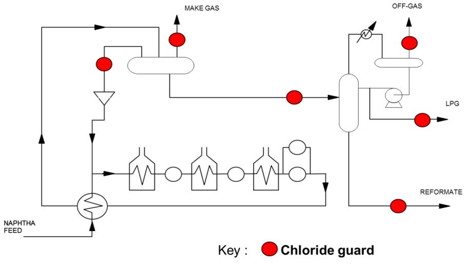
There are three chloride guard locations that will reduce the chlorides in the stabilizer bottoms stream. The most straight-forward choice would be to install a chloride guard directly on the stabilizer bottoms stream. An alternate option would be to install a chloride guard on the unstabilized reformate entering into the stabilizer column. The advantages of this option are that you also protect the stabilizer column itself from ammonium chloride fouling while at the same time removing chlorides from the other product streams exiting the column. This reduces the overall number of beds required if multiple product streams need to be treated. The size of the guard bed for the stabilizer column feed would also be similar to that used solely for the stabilizer bottoms. This means it would provide additional protection with little additional investment required. A third option to consider would be to install a chloride guard on the recycled hydrogen stream. This option would aid in reducing the chloride levels across the entire system, which would include reducing the chlorides exiting with the stabilizer bottoms.
DUNHAM (UOP)
UOP recommends carbon Raschig rings. The key here is to specify to the vendor that this be used for caustic service so that the rings will be formed with the proper binder. If you get the wrong binder, the rings will dissolve. We have a similar service in HF alky units where we use carbon Raschig rings; and there, you have to make sure that the binder is resistant to acid. So, you cannot switch the two. I have seen the carbon Raschig rings ooze out of the tower when a customer bought the wrong binder.
Another material you can use is chemical-grade polypropylene. This is plastic, so it does have temperature limits. If you use this kind of material, you have to be careful not to steamout the tower because this packing is good for the operating temperature of the unit. But if you steam it out, it will melt, and all come out in one piece.
LAMBIE (KBC Advanced Technologies, Inc.)
My experience has only been with the carbon Raschig rings. I have not seen any issues with them in any other sites. My only other comment to add to Daryl’s is that the use of ceramic rings is not recommended because they are not compatible with caustic.
DOMINIC VARRAVETO (Burns & McDonnell)
My question is related to the scrubber. Have there been any comments from the operators of these units with upsets that cause caustic to go backwards into the stabilizer and create plugging in the stabilizer overhead system?
LAMBIE (KBC Advanced Technologies, Inc.)
I have not seen or heard of this happening. Normally there is a check valve in the line to prevent any backflow from the caustic scrubber to the stabilizer.
RICK GRUBB (Chevron Products Company)
We have experienced caustic back-flowing in the overhead receiver drum, so we have installed quick-acting ball valves that activate pressure differential. When the pressure differential gets low enough, it will close the valve.
SCOTT LAMBIE (KBC Advanced Technologies, Inc.)
One-inch OD carbon Raschig rings have been the standard packing material for isomerization unit off gas caustic scrubbers. Use of this packing material has proven to be very effective in minimizing caustic breakthrough and water carryover. Operating the unit per the design circulation flow rates of caustic and water insures proper wetting of the packing material for maximum effectiveness.
The use of ceramic packing material should be avoided as caustic will attack and degrade the material.
DUNHAM (UOP)
UOP’s general guideline is to limit the lead reactor ΔT to 100°F (55°C). This limit is based on our design margins or the heat exchangers around the reactors. That 100-degree limit corresponds to above 5 to 8% benzene in the feed. So, one way to get around that is to recycle or add something to dilute the benzene. Older recycled hydrogen isomerizations will generally have less ΔT than the oncethrough units. We know of some customers who had experience running as high as 110 to 115°F (61 to 64°C) in the lead reactor. A revamp option is to add a benzene saturation reactor upstream of the isomerization reactors.
PATEL (Valero Energy Corporation)
Recycling a stabilizer bottom slip steam back to the feed will dilute the feed, and it will react or reduce reactor delta temperature. The other option, as Daryl suggested, is to install a benzene saturation unit upstream of the reactor.
KEADY (Technip)
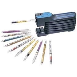
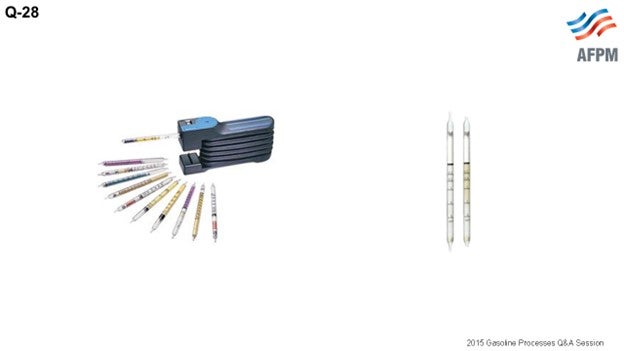
There are three methods for measuring chlorides in LPG streams: UOP 910, UOP 930, and Dräger 2.0.2/A. I have a nice little illustration. You must have proper maintenance of your sampling stations and also of your sampling bombs. For Best Practices, use a sample point a few places within the absorber bed and sample periodically for chloride right through. This frequency will allow historical comparisons. Also, identifying any feed contaminants will help predict the remaining life of the bed.
PATEL (Valero Energy Corporation)
Chloride monitoring in the liquid LPG stream is difficult in the refinery. Typically, the next downstream gas phase stream, which is originating from the liquid stream, can be tested for the chlorides like stabilizer overhead. However, that is not an option for the LPG stream.
One of the best areas monitored is the chloride in the LPG stream. LPG chloride treater chloride content can be estimated through a reformer chloride balance. A reformer chloride balance is achieved when all of the chlorides are accounted for. The reformer releases chlorides into the hydrogen and into the reformer stream. Tracking those values for the hydrogen net gas and the liquid at the stabilizer overhead can eventually allow you to create a reformer chloride balance, as Emerson said. The reformer chloride balance can produce the amount of chlorides at the inlet of the LPG treater. Chloride intake at the LPG treater inlet is estimated based on the balance and can be used in conjunction with the review of the past spent absorbent analysis. A determination can be made as to the appropriate time to make the changeout on the absorbent without experiencing any breakthrough.
JAY RICHERT [(Marathon Petroleum Company (MPC)]
I am just wondering if the panel could suggest the traditional services within a refinery where chloride treatment is necessary. And then, are you aware of any non-traditional stream locations that have been treated in refineries in order to manage overall chloride problem at the site?
LAMBIE (KBC Advanced Technologies, Inc.)
The most common application of chloride treaters is on the net gas stream where the hydrogen is used in many downstream units. In liquid service, the common locations in the reforming unit are the inlet to a stabilizer column or the LPG from the stabilizer column. In some instances, chloride treatment of the stabilizer bottoms may be necessary, depending on where that stream is routed. Some chloride issues may result from poor desalting operation.
RATHING SABAPATHI [Kuwait National Petroleum Company (KNPC)]
The question is not related to this. Is anyone looking to produce TAME from isoamylene or isopentane? Does anyone have any outlook on this issue as to whether it is economical to produce economics or TAME for more gas? Does anyone have any units here? We have surplus isopentane. We are exploring the possibility, so we would like to see if there is an opening.
BURTON (UOP LLC, A Honeywell Company)
Our TAME unit went away when MTBE (methyl tertiary butyl ether) units went away.
LAMBIE (KBC Advanced Technologies, Inc.)
There are several TAME units processing C5 olefins in South America.
FRY (Delek Refining)
Make sure to watch the reformer off gas. We have a cryogenic recovery plant for our refinery off gases, and we make sure to put a chloride guard bed in our dryers. We do not test for chlorides frequently, but we know we get some there.
ABIGAIL SUP (Johnson Matthey Process Technologies)
Many operators do struggle when trying to accurately measure the level of chlorides in LPG streams. The Best Practice is to send LPG samples to a lab that has liquid-phase chloride testing capabilities for analysis of both HCl and organic chlorides. Some locations may have these facilities onsite, while others may require the operator to send samples to a third-party lab for independent analysis.
When sampling for chlorides, care should be taken to choose the appropriate sample container. Chlorides, similar to sulfur, have a tendency to “disappear” in the sample container. A suitable lining in the container can help ensure that the level of chlorides is accurately measured during analysis. Also, the chosen sample container should be suitable for vapor samples, commonly referred to as a “sample bomb”. The sample will likely contain a mixture of both liquid and vapor. Some have found it can be difficult to ship LPG samples offsite. Johnson Matthey can help coordinate sampling, so it may also be worthwhile to check if your catalyst supplier also offers assistance.
An alternate option to consider, if liquid phase chloride testing capabilities are not available, is to analyze the LPG sample in the vapor phase. This can be accomplished by flashing the sample into a sample bag. The flashing should be performed under a laboratory hood or other means of ventilation, while taking all proper safety precautions. It is important to ensure that the sample is fully vaporized so that an accurate measurement can be obtained. In certain cases, this may require some form of additional heating. Once the sample is in the gas phase, detector tube technology can then be used to determine the concentration of chlorides present. Keep in mind the concentration results using this method will be in ppmv (parts per million by volume). It is recommended to convert the concentration back to ppmw as is customary for liquid applications. Also, care should be taken to measure both HCl and organic chlorides as some LPG streams may only have organic chlorides present.
To determine when an LPG chloride treater/guard bed should be changed, a routine sampling protocol could be established. This sampling can include periodic measurement of the chloride concentration on both the inlet and the outlet of the chloride treater/guard bed. The inlet sample analysis would allow for calculation of the expected saturation of the chloride media. The amount of chloride that can be absorbed prior to breakthrough can be estimated based on the expected capacity of the material for a particular application. The expected capacity can be provided by the absorbent supplier. The outlet sample analysis would confirm whether or not a breakthrough has occurred.
As sampling can be cumbersome, another option would be to only take baseline chloride measurements and then calculate the life of the bed based on the expected capacity, as discussed above. The baseline chloride concentration and projected flowrate across the bed over time can be used to calculate the expected life of the bed. Changeout can then be scheduled to occur during a downtime that is close to the time breakthrough is expected to occur.
GINGER KEADY (Technip)
Three methods [used?] to analyze the chlorides in LPGs:
UOP 910 method for the organic chloride: This method is for determining total chloride in gaseous hydrocarbons or liquefied petroleum gas (LPG) at concentrations ranging from approximately 1 to 1000 mg/mL (milligrams per milliliter) for gas or mass-ppm for LPG (liquefied petroleum gas). Except for fluoride, other halogens present are calculated as chloride. Chloride cannot be determined quantitatively if sulfur is present at concentrations greater than approximately 1 mass-%.
UOP 930 method for the total chloride (but Axens has no feedbacks regarding this method): This method is for determining the sum of organic chloride and hydrogen chloride (HCl) in LPG and refinery gas streams at concentrations ranging from approximately 0.02 to 1000 mass-ppm (mg/kg) for LPG samples or 0.02 to 1000 ng/mL for gas samples. Other halogens present are determined as chloride.
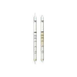
Dräger Tube Chlorine 0.2/A: