Question 5: Automobile manufacturers are considering requiring the use of higher-octane fuels in order to meet a mandated increase in Corporate Average Fuel Economy (CAFE) standards. What strategies might you employ should demand for higher octane gasolines increase?
KEADY (Technip USA)
I think this is a great question, and I found it very interesting to look into this. Over the years, gasoline and engine manufacturers have worked together to give us the type of cars we have now and the type of fuels we buy. There is a push to design the engines with higher compression, so that requires octane. So first you use technology, because that is my background. Of course, I am going to say that we need process design and technology to put in technology to take your straight chains and make them into branch chains to give you a higher octane. But another consideration is changing the octanes that we make available to the market.
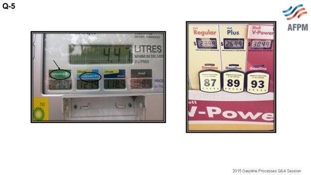
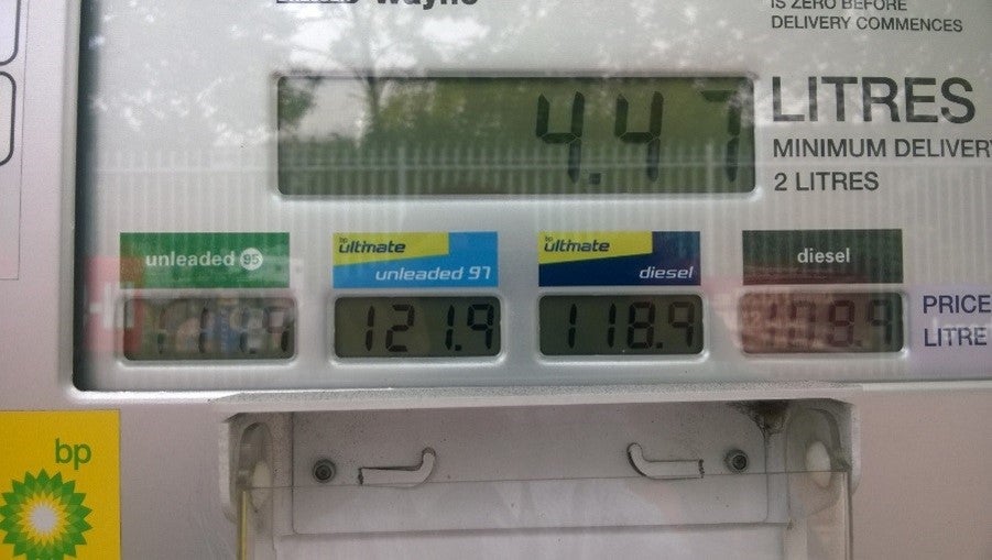
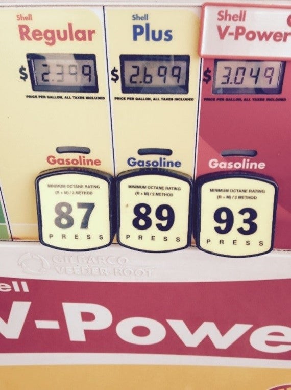
A friend of mine took a picture of the petrol available in the UK, and I took a picture at a gas station near I-10 and Kirkwood where I work at Technip. In Europe, the standard is EN 228 with one gasoline octane. Now when you look at the pump, it says, “95 octane” and the other grade says, “97 octane”. So sometimes people say, “Oh, they have higher octane in Europe.” They do not have higher octane; they just report RON octane versus here in the U.S. where we have 87%, 89%, and 93%, which is an average of the RON and the MON octane.
What they were telling me there is that the lower-octane gas is available in the U.K., but they get to charge the same price as they do for the mid-range octane. The reasons are that no one uses it much anymore and because it is a niche market for those who have vehicles that still use the lower octane. Then of course, they provide 97%, which is in line with our higher-octane gas; so this is a possibility.
If you want to get rid of the naphtha which might have some of the lower-octane, you can always export it as olefin feedstock; that is, if you are in a location where this is available. Also you can reform coker naphtha, but you have to watch for RON loss there.
LAMBIE (KBC Advanced Technologies, Inc.)
From a fuel standpoint, higher octanes and increased miles per gallon do not necessarily go hand in hand. Two fuels can have the same octane but have different heat contents or BTUs (British thermal unit) per gallon and yield different miles-per-gallon performance. To increase the miles per gallon of the fuel itself, one needs to increase the heating value or heat content of the fuel. One strategy to increase the heat content of fuel is to increase severity/octane in reformers. The resulting higher aromatic content reformate will have a higher energy density; and hence, will provide improved fuel efficiency. Most reformers in the U.S. have the capability to increase reformer severity as they have been reduced as a result of the ethanol mandate. Alternatively, those refiners bypassing heavy naphtha to the gasoline pool can process the naphtha in the reformer to increase the heat content. One must consider increased benzene and aromatics production from increased reformer feed or severity to make sure the increases do not prevent meeting gasoline pool specifications.
Another strategy would be to consider the use of secondary biofuels, such as butanols. Butanols have a higher energy content, by approximately 30%, than ethanol and a lower oxygen content, which allows for blending about 12.5 vol% versus 10 vol% into the pool. In addition, butanols have a low RVP which allows for blending lighter, more volatile components. Butanol’s low water solubility would allow for blending the component at the refineries. Both increased reformate and butanols would contribute higher octane in miles per gallon to the fuel.
Some other areas to increase octane would be C5/C6 isomerization options, as long as the RVP is not limiting. There have been some recent developments in the C7 paraffin isomerization technology versus reforming, which “increased the yields and overall octane” of naphtha. That should be investigated for its merit.
Incremental alkylation capacity will continue to be very profitable.
MEL LARSON (KBC Advanced Technologies, Inc.)
One difference between the markets in Europe and the U.S. is that in the U.K., they actually have tailpipe testing. In the U.S., there is very limited actual tailpipe emissions testing. The manufacturer may show, via internal testing, that it has achieved the target CAFE standard using premium gasoline. But then, the consumer goes out and puts in regular gasoline. So as long as there is a price differential, one has to map out what the consumer will do, as opposed to the actual tailpipe emission spec. This will not have a big impact until every station, or every vehicle is checked annually for tailpipe emissions, and then we will be being driven to a certain fuel standard.
WARREN LETZSCH (Technip USA)
My experience in the past with Europe is that frequently European refiners were really motor octane-limited, not research-limited, in terms of blending their gasoline. For instance, if you could make more alkylate, it would be very, very helpful in Europe. So I would to like the ask the panel if any of you are seeing any C5 alkylation helping with vapor pressure and if there is possibly another way of being able to get lighter ends into gasoline pool. The other observation I have made is that it seems as if half of the reformers today seem to be running for hydrogen rather than for octane anyway. In fact, I did not really realize that you could run a CCR (circulating catalyst regenerations) unit in such a low octane number; and again, it seems like there is a lot of room there for things. I sure would like to hear your comments.
DUNHAM (UOP LLC, A Honeywell Company)
We have seen a lot of interest in C5 alkylation, particularly when crude prices were high and natural gas price was low and we were getting a lot of cheap isobutene on the market. That is a real economic driver for C5 alkylation. If you can get cheap isobutene, it makes sense to alkylate the C5. You get a little vapor pressure reduction. One of the factors in alkylating C5 is how much isopentene you make. There is a lot of hydrogen transfer and C5 olefin conversion to isopentene, and then you can consume more isobutene. People are starting to look at that option.
Just about the time we thought people were going to move into this, there was a little drawback on propylene economics; so people started alkylating propylene to fill their units instead of C5. However, we may get back in that situation where C5 is attractive, if they start selling propylene more and isobutene price stays low.
DOMINIC VARRAVETO (Burns & McDonnell)
I want to comment on the C5 alkylation issue that someone just brought up. We have worked with some customers who are looking at sulfuric acid C5 alkylation. Our experience is that there is no one out there doing this to a very great extent and that some of the operators will try to co-process, but the best results are achieved from a dedicated C5 alkylation arrangement. So co-processing is a compromise type of an opportunity; dedicated processing works better.
ERIC YE (DuPont Clean Technologies)
Even without potential regulatory increases in minimum octanes, in a low price gasoline environment, it seems clear that lower prices result in premium gasoline demand. As such, refiners should already be employing strategies to increase the production of high octane blendstocks. As with any strategy, the impact of any moves to increase the octane pool needs to consider the impact of modifications on the total refinery economic return. Such concerns include yield shifts to non-gasoline products, such as fuel gas and LPG; gasoline RVP constraints; butane containment; and if applicable, petrochemical operations, to name a few.
Excluding the increased use of ethanol, which is currently limited by the current E10 blendwall restrictions, some options a refiner may consider increasing the octane pool include:
-
Reducing the Volume of Low Octane Blendstocks: Straight run naphtha (SRN) is one of the lowest octane blendstocks in a refiner’s gasoline pool. Some refiners, particularly a number in overseas refineries, employee a strategy of cracking SRN in an FCC. While cracking SRN in the FCC reduces the amount of low octane naphtha available for gasoline blending, it also generates an increased volume of light olefins that can be alkylated to create a high octane and low RVP gasoline blendstock. With butane prices selling at significant discounts to gasoline, such an action could prove to be quite lucrative for the refiner provided that such an action does not adversely affect the refinery FCC or fuel gas balance.
-
Employing Isomerization: SRN can be isomerized to realize a 10-15 octane number improvement. However, the relatively high RVP of the isomerate (15 to 20 psia) restricts the volume of isomerate that can be blended into the gasoline pool. In addition, the upgrading process results in modest C5+ yield loss and an increase in LPG and fuel gas production.
-
Increasing Alkylate Capacity: If a refinery has light olefins (C3=, C4=, and C5=) available, consideration should be given to maximizing alkylate production. While C3 and C5 alkylation produces a product that is lower in octane than high-octane C4= alkylation, the alkylate still has an octane significantly above regular unleaded (RUL) gasoline. In addition, the low RVP of the alkylate allows a refiner to blend in high octane and high RVP blendstocks, such as butanes, to further boost the octane pool. For refiners with existing alkylation units, modifications to the configuration or operation of the alkylation unit can often generate 1 to 3 octane number improvements of the overall alkylate product. The modifications are specific to the type [HF or H2SO4 (sulfuric acid)] technology and the particular configuration, but some options for sulfuric acid alkylation units include external feed chillers, segregated contactors, or high efficiency bundles.
-
Increasing Reformer Severity: Increasing reformer severity is an option to increase the octane pool. However, such a strategy must take into account reduced C5+ yields and increased fuel gas and LPG production.
-
Hydrocracker Heart Cut: Most hydrocrackers have the ability to produce two separate gasoline boiling cuts: light heart cut and a heavy heart cut. The low aromatic content of these streams results in a blendstock that is relatively low in octane. The heavy heart cut normally possesses a high N+2A and thus produces a high-octane reformate with minimal C5+ yield loss and LPG/fuel gas production. Depending on the particular refinery option, the light heart cut could be directly blended into gasoline and the reformer supplemented with SRN that possess a higher N+2A.
SCOTT LAMBIE (KBC Advanced Technologies, Inc.)
C3/C4 Paraffins Processing: Dehydrogenation of paraffins and alkylation of the olefins produced will provide a premium quality, high-octane blendstock for the gasoline pool. Additional alkylation capacity would be needed to accommodate the increased olefin production. Alternatively, isobutane can be dehydrogenated to produce isooctene and then saturated to produce isooctane, if desired. This process produces a very high-octane gasoline blendstock.
Similarly, converting LPG to aromatics will produce a high octane, but highly aromatic product is a processing option. The benzene content would be very high and would need either extraction to produce a benzene product for sales or alkylation with a light olefin to produce a gasoline component. Again, the economics of producing gasoline via this route may be hard to justify.
C5/C6 Processing: Increasing light naphtha octane via isomerization technology has significant potential but comes at the expense of high RVP, which makes it difficult to blend into the gasoline pool.
There are a number of isomerization unit configurations that can increase the octane of light naphtha. A few options are as follows:
-
Adding a deisopentanizer on the light naphtha can add from 1 to 2 octane numbers to the combined isomerate, depending on light straight-run (LSR) iC5 content.
-
Recycle options, either mol sieve or a deisohexanizer (DIH), can increase product octanes to the upper 80s.
-
Super deisohexanizer to recycle nC5 to extinction, in addition to recycling nc6 and most methyl pentanes, can increase isomerate octane to the low 90s.
The increase in RVP may become problematic or prohibitive to light naphtha upgrading options.
Reforming: Many refineries have the ability to increase the feed rate to the reforming unit by reducing the amount of heavy naphtha sent directly to blending. In addition, many reformers have the capability to increase the severity or octane of reformate as well. This flexibility resulted from compliance with the ethanol mandate that increased the octane of the gasoline pool considerably. The combination of increased severity and throughput in the reformer helps increase the octane and heat content of the gasoline pool and, as a result, increases the fuel efficiency or miles per gallon.
Higher reformer throughputs and severities will result in increased aromatics and benzene production that will need to be managed in the gasoline pool. Additional technologies – such as extraction, saturation, or alkylation – may be necessary to reduce benzene levels to meet gasoline specifications.
C7 Processing: The merits of isomerizing C7 paraffins, as opposed to reforming, warrants investigation.
Alkylation: Many units today are at or near maximum capacity. Increasing I/O (isobutane/olefin) ratios will increase alkylate octane incrementally but will unlikely have a major impact on the pool octane. Refiners constrained on capacity may consider lower I/O ratios to accommodate more feed. However, this will come at the expense of lower octane. Refiners not constrained on capacity may consider alkylating propylene or amylenes; again, at the expense of octane. However, these feedstocks will compete with their alternate dispositions. In addition, the alkylation unit may need to be revamped to accommodate the propylene/propane and pentanes/amylenes feedstocks.
Additional alkylation capacity will continue to be very economical. The most likely source of olefin feedstock is an FCC unit, which would most likely require additional feed. This will be an economic decision based on crude selection and overall refinery economics.
FCC: Additional feed can yield additional olefins for alkylation units. The source of FCC feed will have to be rationalized with crude economics. Provided economics are positive, feed rate additions – and hence, olefins production increases –may coincide with alkylation capacity additions. Maximization of ZSM-5 to produce olefins for alkylation will have the added benefit of increasing FCC naphtha octane. The gasoline pool aromatics and benzene content need careful consideration.
sobutanol’s low blend RVP is a significant advantage versus ethanol as it would allow for blending more light naphtha, isomerate, or butane to the gasoline pool. The lower oxygen content would allow for blending up to 16.5% isobutanol while maintaining the same oxygen content in the gasoline pool as 10% ethanol. This increased volume results in increased octane to the pool overall, as well as doubles the RIN (renewable identification number) credits from 10 to 21.9 per gallon of gasoline. The ability to blend isobutanols at the refinery is another big advantage for refiners as this allows for minimizing giveaway in gasoline blends. Isobutanol’s energy content is approximately 17% higher than ethanol, which improves the average mpg (mile per gallon) of gasoline.
GINGER KEADY (Technip)
“The efficiency of gasoline engines depends on the octane number, but that’s not something that’s changed in quite a while,” says Raymond Speth, a research scientist in MIT’s (Massachusetts Institute of Technology’s) Department of Aeronautics and Astronautics. “If [manufacturers] know the gasoline is higher-octane, they can design engines to have a higher compression ratio, which would make the engine smaller and more efficient, both of which are a benefit.”1
Suggested strategies to provide higher octane gasoline are the following:
-
Use technology to create branched paraffins for higher octane blending components by sending most light straight-run and saturated gas naphtha to isomerization.
-
Base gasoline octane on RON. Octane rating in Europe is RON and the U.S. is the average of RON and MON (MON designed for carbureted engines rather than modern, fuel-injected engines). The difference indicates sensitivity to changing operating conditions. BS EN 228 95 RON is a legal standard. No MON is posted, but 85 MON minimum is given in BS EN 228. There is no requirement for 97-98 RON, but it is provided at few select locations. The refiners are allowed to sell 90 RON to niche market (older cars), but octane is not easily available and is not cheaper.
-
Reduce the number of octane gasolines available on the market, i.e., drop lower octane gasoline.
-
Export light naphtha to be used as olefins feedstock.
-
Reform coker naphtha but watch the RON loss with the benzene removal.
Question 6: Do LTOs contain higher concentrations of nitrogen? If so, how has this higher concentration effected gasoline processing units?
PATEL (Valero Energy Corporation)
The LTOs generally do not contain a higher concentration of nitrogen. LTOs are typically characterized as light, sweet, low-sulfur, low-nitrogen crudes. For example, the Eagle Ford and the Bakken nitrogen typically contains less than 2 ppm. Nonetheless, the gasoline processing units are impacted when refineries process higher percentage of the LTOs because of the crudes. The LTOs have lighter and heavier naphthalenes, which causes an increase in the feed rate to the naphtha hydrotreater and to the isomerization and reformer units, producing higher barrels of the isomerate and reformate in the refinery gasoline pool. LTOs can also cause challenges for blending the light straight-run naphtha and its handling because of the higher rate and vapor pressure. Also, LTO crudes are higher in paraffins, so the reformer feed will be leaner with the lower end, which that could result in requiring more severity and lower product octane. Also, the higher naphtha yield could result in a directionally lower rate to the FCC and alkylation unit, and that could cause underutilization of those units and reduced contribution to the refinery gasoline pool.
GINGER KEADY (Technip)
It is not easy to get ahold of some of these assays. People keep them very close. I have seen one between the initial point and 390°F. In that case, there was no reported nitrogen. And in between 390°F and 480°F, the reported nitrogen was around less than 20 ppm total nitrogen.
Question 7: Recognizing that onstream factor is an important component of margin capture, what are the common areas of improvement for each of the gasoline processing units to reduce downtime or increase turnaround interval?
KEADY (Technip USA)
At the very beginning, we talked a lot about how to improve onstream factors. Since my background is technology and engineering, I have seen everything: from clients who did not want to spend any money to clients in the Middle East who were willing to put in empty, spare reactors just so they could get four years and almost push five years. They were willing to install spare compressors, maybe more so than clients here in the U.S. Also, we think that the alkylation unit will have to be able to operate within the same turnaround schedule as the FCC, so you can keep that unit. There are corrosion issues in alkylation units that will have to be addressed. There is fouling in the naphtha hydrotreater, which may be from nitrogen and air contamination from tankage and transport.
Utilities are often overlooked. I went to speak with a colleague, who is our utility expert, and he said, “We do all these things in the process area, and then the utilities sometimes let us down.” Air compressors should always be spared. Reliability sometimes is due to overuse and the fact that people do not maintain compressors as much as they should. The system needs a backup power source. Nitrogen is an important system because it is used for purging processes. It needs extra capacity. And then for fuel gas, you need many sources of fuel gas to avoid problems resulting from insufficient fuel gas.
LAMBIE (KBC Advanced Technologies, Inc.)
Maintaining good water, chloride, and nitrogen control around the units will help minimize fouling and corrosion in equipment, which will lead to improved onstream factors. Having a good reliability KPI (key performance indicator) monitoring program that includes equipment replacement strategies, as well as doing a good job cleaning or passivating equipment, will prevent premature fouling and possible failures due to corrosion. You also need a good catalyst management system for naphtha hydrotreaters that includes catalyst bed grading, scale traps, or outlet collector design to prevent premature shutdowns due to pressure drop. In fact, there is going to be a paper this afternoon by Valero which addresses this particular topic. Also, take advantage of windows of opportunity. If there is a mechanical issue in the reformer that caused a shutdown, use that time while the unit is down to do a skim of the NHT (naphtha hydrotreater) catalyst. This requires good maintenance planning and scheduling practices.
As far as turnaround time intervals, there is not a lot of incentive to go beyond five years. Going beyond five years between turnarounds would require a full inspection of each turnaround, per the 10-year API inspection guidelines. Maintaining a five-year cycle allows you to inspect half of the equipment each turnaround, thereby shortening the turnaround time. Having an integrated Process, Mechanical, and Contractor plan and ensuring that everyone is on the same page will provide for an efficient turnaround. You also want to make sure you have the correct spares in inventory so you will not have to go searching around and ordering new parts, if needed. Finally, you should have good bolt-up procedures for flanges to avoid leaks and potential re-bolting of flanges.
FRY (Delek Refining Ltd.)
We have a Kellogg-style sulfuric acid alkylation unit, and we recently made some efforts to improve certain aspects of our alkylate wash system. Based on our experience, I would say that you need to make sure that you understand the entire process. Small changes in one part of the process can have great impacts elsewhere. The change that we made did not help our reliability. In fact, it decreased it. So, make sure you have a good understanding of how the entire process works and how a small change might impact it. Do not do it piecemeal. Make sure that you have consider the big picture.
KEVIN PROOPS (Koch Industries, Inc.)
Those were great answers from the panel. Thank you. I will put on my old Solomon hat for a minute. A good target for operational ability is around 97%. The question asks about increasing turnaround interval. I agree with Scott’s comment that interval may not be the correct focus. From our Flint Hills Refinery data, I know that once you get four- or five-year intervals, you are probably in good shape. But really, the turnaround duration is more important. Even the really good performers that have fairly short downtimes often have opportunities, maybe in startup and shutdown, when they are really pushing the mechanical window as hard as possible but not paying enough attention to how much time it takes to start up and shut down a unit.
UNIDENTIFIED SPEAKER (Indian Oil Corporation)
I have a specific question about the CCR unit. I am not talking about the downtime for annual maintenance; I am asking about catalyst fines management. What are the best times between two catalyst-saving operations? Could we have a cycle end of two years with a license that can go up to four years with room required to see and remove the fines? So, I would like to ask the panel their opinion about a good run-length for the catalyst.
ROBERTSON (AFPM)
His question is: How long can you run a CCR between the time that you screen or remove fines from the catalyst?
WAYNE WOODARD (Valero Energy Corporation)
For our CCR units, we target mechanical availability of eight to 10 years. What we do for every CCR turnaround is inspect Reactor One and document how much it has plugged over the course of the cycle. I wrote a paper stating that although the unit may be on a five-year cycle. I will offer an opinion based on the plugging in Reactor One that this unit can operate reliably for up to 10 years, possibly shorter, depending on the findings of the Reactor One inspection). It is common to go over a five-year turnaround cycle to capture economics.
MEL LARSON (KBC Advanced Technologies, Inc.)
Going forward, I think we will have to consider all of the new EPA guidelines and regulations that are coming into play. The industry may find we not pushing units up against the hydraulic limit, even with the economic value for running the units. With all of the environmental guidelines, such as opening up vessels and emissions allowances, the industry might cut rates with the need for better reliability because of the lower tolerance of emissions excursions and the associated higher cost. Just a point to consider.
PATRICK BULLEN (UOP LLC, A Honeywell Company)
Related to the CCR question and Wayne’s comment, to attain a five- to eight-year run without fouling the lead reactor, you really have to pay attention to the Best Practices on the regen side to make sure you are continuously monitoring your regen screens and not allowing them to plug up too much. This requires taking an outage on the regen side to clean the screens while you are running the platforming unit. Ensure that you are separating your catalyst fines efficiently by checking to see if you are getting whole pills overhead. These Best Practices are critical to get that longevity.
GARY HAWKINS (Emerson Process Management)
We have seen considerable interest in automation to monitor asset health, such as heat exchangers and process pumps, specifically to lessen the surprises of mechanical equipment failure. The business drivers of these investments are to improve onstream availability and the advent of wireless field devices has lowered the capital cost hurdles of adding instrumentation.
SCOTT LAMBIE (KBC Advanced Technologies, Inc.)
Turnaround time intervals approaching 60 months are becoming more frequent as processes and procedures improve over time. The incentive to extend the turnaround cycle beyond 60 months does nothing more than prolong turnaround times. All refinery equipment should be inspected within a 10-year period. Beyond 60 months (five years) between turnarounds, all equipment would need to be inspected every turnaround, which increases the turnaround time. Inspecting half the equipment every five years allows for shorter turnaround times, and complete inspection of all the equipment within a 10-year period.
Some of the common areas that can help improve onstream factor and unit reliability are listed below.
-
Maintain good water, chloride, and nitrogen control to minimize corrosion and fouling in exchangers, towers and compressors including
-
Use chloride guards' beds to reduce salting and fouling issues and
-
Apply sufficient/effective water-wash of reactor effluent trains and stabilizer towers, where applicable.
-
Perform adequate instrument/emergency shutdown testing and providing appropriate instrument redundancy.
-
Have a good Reliability KPI Monitoring Program that includes an equipment replacement strategy and a corrosion control program.
-
Minimize thermal cycling to improve equipment life and minimize leaks.
-
Identify and have in stock critical spare equipment.
-
Perform compressor strengths and weaknesses audits
-
Identification of adequate instrument availability to measure critical parameters,
-
Trip system checks,
-
Verification of spare parts/spare rotor availability, and
-
Fouling protection needs.
-
Good regeneration procedures for semi-regen/cyclic reforming units to minimize corrosion and fouling post regeneration.
-
Assure adequate corrosion control in the CCR section.
-
Good furnace refractory and skin temperature measurement and monitoring.
-
Effective catalyst life management on naphtha hydrotreaters to account for poisons buildup
-
Catalyst bed grading, outlet collector design, scale traps, etc. in NHTs and
-
Good corrosion control upstream of the naphtha unit.
-
Have a reliable steam/power supply for all units.
-
Be opportunistic:
-
Requires good maintenance planning and scheduling.
-
Take advantage of windows of opportunity to do maintenance.
-
For example, if the reformer has a mechanical problem and needs to shut down, fix, replace, or repair a piece of equipment or skim the NHT reactor during the shutdown time.
Some of the common ways to reduce turnaround time are listed below.
-
Integrate the process, mechanical, and contractor plans.
-
Ensure good corrosion control to avoid unplanned corrosion, leaks, or fouling of compressors during the shutdown.
-
Utilize the best regeneration procedures for semi-regen units to maximize catalyst online stability in the minimum amount of time.
-
Use good equipment cleaning and passivation.
-
Use the best quality swing valves in cyclic reforming units.
-
Ensure the correct spares inventory for reactor/vessel internals.
-
Use Best Practice bolt-up procedures to avoid leaks and repeat bolt tightening by using controlled bolting on higher pressure flange and using correct gaskets.
GINGER KEADY (Technip)
Technology and engineering design help improve onstream factors. Depending on the cost tradeoff, sparing philosophy increases onstream time. Some client's spare reactors and compressors.
The alkylation process must match FCC (now three to five years between turnarounds) with corrosion management in alky units that operate out of the design conditions.
Fouling occurs in NHT due to nitrogen and air contamination from tankage and transport. Fouling and corrosion due to chlorides is managed with continuous water-washing. Waterwash pumps should be spared. The waterwash rate depends on the NH3 and H2S in the feed, approximately 5 to 10 vol% of feed rates. Overcooling in reactor effluent cooler should be prevented to reduce fouling.
These support utilities are sometimes overlooked:
-
Instrument Air: Air compressor is always spared. Reliability is reduced due to overuse, as well as lack of maintenance and uneven load share. The system needs backup power.
-
Nitrogen System: Nitrogen used for purging processes requires spare capacity.
-
Fuel Gas: Several sources of fuel gas are required, particularly for gas turbines.
Question 8: How will the recently announced EPA regulations on emissions impact your refinery operation and specific technologies [FCC, hydroprocessing, coking, CDU/VDU (crude distillation unit/vacuum distillation unit), reforming, etc.]?
PATEL (Valero Energy Corporation)
Refinery risk and technology rules were adopted last week on September 29th. They are expected to have a significant impact on the refining industry. The rules require additional control and monitoring of the emissions from the refineries and the emission reporting that is available to the public and other neighboring communities. The revisions include newer requirements for the lead coker flaring operations and fenceline monitoring and the elimination of some of the startup/shutdown emissions in the malfunction provision. The delayed cooker depressuring standard provision states that the coke drum cannot be vented to atmosphere until a pressure of 2 psig (pounds per square inch gauge) or lower, or the refinery average, is reached.
For the existing coker, this will be averaged over 60 cycles. For the new cokers, the standard will apply for each event. The Southern California AQMD (Air Quality Management District) already implemented Rules 11 and 14 last year that limit the depressuring drum pressure to 5 psig for each event. And starting January 1st, 2017, it will go down to 2 psi for each event. Depending on the blowdown system, significant modifications could be required to meet this requirement.
The flare monitoring and operations that are used as a control device for the hazardous air pollutant streams are subject to a new monitoring and control requirement that is designed to guarantee that the flare operates with 98% destruction efficiency at all times. Composition monitoring and automatic control will be required on all flow streams going to the flare, including steam, purge gas, and acid gas to ensure that certain BTU and combustion characteristics are achieved.
Fenceline Monitoring: All refineries will be required to deploy a series of passive absorption tubes around the perimeter of the facility to monitor for benzene. The proposed standard is 2.8 parts per billion on the rolling annual average for an average of 26 events per year. Any incident could trigger a root cause and corrective action analysis to reduce the emissions. All sampling results will be available to the public. Some of the root cause analysis and action plans must be submitted to the EPA.
The SSM (startup/shutdown malfunction) Emission: All sources and regulations must be in compliance with the emission standards at all times, including for the startup/shutdown and the malfunction. Limited exceptions exist for FCC and sulfur recovery units. Otherwise, FCC units that are equipped with scrubber and CO (carbon monoxide) boiler are expected to comply all the time.
Under the proposed revision, the recommended gassing to the atmosphere cannot occur until the vapors are below 10% LEL (lower explosive limit) or pressure is below 5 pounds. The monitoring of the atmospheric PRDs (pressure-relieving devices) will be required. The release event must be analyzed from these devices to determine the cause and remedy, and there is a firm limit that no more than three events in the three years per device will be allowed. The deadline expected for the fenceline monitoring is December 2017, and the provisions will be effective the following year: December 2018.
SIM ROMERO (KBC Advanced Technologies, Inc.)
There is a P&P tomorrow at 2:00 to discuss methods of addressing the two-pound limit on the delayed cokers. It can be expensive or relatively inexpensive, depending on your choice of equipment and equipment configuration. I will be giving that presentation.
DOMINIC VARRAVETO (Burns & McDonnell)
I just want to point out that in Day 1 of the “Conference Daily” published by Hydrocarbon Processing that is available to everyone, there is an article on page 12 authored by Blake Soyars, Jim Corbit, Greg Neve, and Mark Lockhart from Burns & McDonnell addressing this subject.
Question 9: Is there a limit on the amount of time acid can remain stagnant in the reaction section of the alkylation unit? What adverse effects may occur if this limit is exceeded? What issues could arise on a restart from a stagnant-acid condition?
FRY (Delek Refining Ltd)
We have found that if we can bring the unit down in a controlled fashion – specifically, if we can clean up the acid by circulating isobutane for a few hours and clear the acid of any reactants, then we can let it sit there for 24 to 36 hours, maybe even 48 hours, without any kind of issue. However, if the unit came down because of something unexpected (e.g., a power outage), you will not have an opportunity to circulate isobutane, nor will you be able to bring the unit back up within 12 to 24 hours. At that point, you might need to consider dumping the acid because it could form polymers and acid-soluble oils. If you go for an extended period of time, even beyond that, then the acid might even set up and you will not be able to flow anything. So the practice we use is that if the shutdown is controlled, then you will have a 36 to 48 hours. If it was not controlled, then get ready to dump the acid after 24 hours.
DUNHAM (UOP LLC, A Honeywell Company)
Fortunately, AGIP (Azienda Generale Italiana Petroli/General Italian Oil Company) is a little more stable. And if you are not bringing in olefin feed, there is usually no problem with letting the reactor just sit. The HF alkylation reaction takes places very quickly. HF mixes readily with hydrocarbons, and it separates readily from the hydrocarbon. So, unless you are going to be down more than about four weeks, it is okay to just let the reactor sit. If you are going to be down for an extended period of time, we recommend that you dump the acid, just from the safety standpoint, to get it out of the reactor loop where there are a lot more connections that can leak. Get it into a storage drum where you can isolate it from the process.
There are some reactions that can take place. The polymer that is in the acid can get a little heavier. There are other problems that may happen if you have leakage into the unit. So what we recommend on startup of the unit is that if the acid and hydrocarbon are still on the settler, you must get isobutane recycle established to ensure good acid circulation. Then, check the acid strength to make sure you have acid within your target strength. If you do not do this, there is a chance that when you bring in the olefin feed too quickly, the unit could run away.
BURTON (Motiva Enterprises LLC)
For sulfuric acid plants, our recommendation is very similar to what Emerson said. For a controlled shutdown, the reactors are flushed with isobutane to consume reactive components contained in the acid. The reactor will then store isobutane-full of the acid transferred to and stored in the settler. If the reaction section will be back up in, say, less than a week, then we will not dump the acid. If the down time is anticipated to be any longer, then we recommend removing the acid from the reactor system.
RANDY PETERSON (DuPont Clean Technologies)
This is a frequently asked question from those refiners who have STRATCO® sulfuric acid alkylation units. During a typical FCC three- to four-week turnaround, many refiners choose to minimize work within the alkylation unit by performing any reaction zone maintenance either before or after the FCC shutdown period. If the entire alkylation unit reaction zone or just a portion of it will not be entered during the shutdown, we typically recommend NOT neutralizing that equipment and leaving the acid in-situ.
However, we DO recommend pushing the acid from the Contactor™ reactors up to the acid settlers and stopping all feeds as they could potentially contain wet hydrocarbon. Hydrocarbon can be left in the reaction zone as well, as long as the relief system is functional. During this period, the reaction zone should not be entirely liquid full in order to leave room for thermal expansion.
The neutralization of carbon steel removes the protective layer of iron sulfate which will form again after exposure to acid. Avoiding unnecessary neutralization avoids this metal loss. Leaving acid in the reaction zone saves labor hours (shutdown and startup), as well as the cost of the acid.
Once the acid is within the acid settler(s), it will slowly degrade and can form acid sludge over time. The major concern is that this sludge can clog small bore piping and fittings and foul the vessel internals. The decomposition reaction rate increases with temperature, so a refiner in a cool climate can safely store acid longer than in a warm climate. We have not heard of problems occurring when refiners have stored intermediate-strength acid (92%+) in their acid settlers for three to four weeks.
H2SO4 + CHx → H2O + SO2 + CHx-2
If the duration of storage is expected to be significantly longer than three to four weeks, then we recommend draining the reaction zone of all acid and neutralizing it.
Question 10: Where is carbonyl sulfide found in alkylation units? What effects can it have on the unit, and what are the prevalent management strategies?
FRY (Delek Refining Ltd)
Again, I am focusing mostly on sulfuric acid units because that is where I have experience. Carbonyl sulfide (COS) is a noncombustible gas that will follow propane and propylene. So, if you are running all of your FCC olefins, then you will get it into the reactor and into the refrigeration section. If you are using a C3/C4 splitter on the front end, then it will go out with your propylene product overhead of the splitter. It can cause issues in both locations. We have had experience with COS hydrolyzing to form H2S and failing copper strip corrosion tests on the propylene product stream.
The other location where you can have issues – one where we do not have much experience, but I understand others do – is when COS gets in the refrigeration section. It can hydrolyze with any water, form H2S, and cause copper strip corrosion failure in your propane stream. One way to deal with this issue is to use solid KOH (potassium hydroxide). At our facility in Tyler, we have never had issues with our propane because we do have KOH beds. So, if any COS does slip in with the feed, it is neutralized there and does not cause any issues. Having the proper feed treaters – say, using a DEA (diethanolamine) amine – to treat your feed will also help.
I also understand that there are a number of facilities which have had success using alumina or mol sieve. The objective with those methods is to hydrolyze the H2S at that location and then neutralize it with an absorbent before it goes into your feed. If you use an amine process to treat your alky feed, then consider using DEA DGA (diglycolamine?). MEA (monoethanolamine) will react and form a non-regenerable urea. You can try using MEA as an additive in other applications, but certainly not in your amine unit. MDEA (methyl diethanolamine) is not effective in removing COS.
KEADY (Technip USA)
Emerson did a great job and basically covered everything. I have a lot of experience removing COS because many of our high propylene FCC units to produce polymer grade propylene. We designed contaminant removable beds. The sequence of the beds is very important. You need to work with your design engineers to get the sequence of the beds correct. In many of our units, we use Selexsorb™ COS to ensure the quality of propylene. And you are right: It does follow propane and propylene.
DUNHAM (UOP LLC, A Honeywell Company)
In an HF alky unit, the carbonyl sulfide is one of the few sulfur compounds that can get all the way through the reactor unreacted. When it goes out with the propane stream, it will hydrolyze in the alumina treater because it is running 400°F, there is water and a catalyst present, and it will form H2S there. The H2S will be captured in the downstream, solid bed KOH treater, because that is where the water will dissolve the KOH, and then that will absorb the H2S. There is a safety concern here that when you drain that brine of KOH in water, it contains H2S. Most people do not understand that H2S can be present in an HF alky unit. When that gets into the sewer, if it gets neutralized anywhere or goes into an acidic situation, the H2S will sprung. So, this has proven to be a safety concern in HF alky units. We have had refiners whose H2S detectors have gone off while they were draining this brine off the KOH treater.
ADRIAN SKIPPER (Phillips 66)
How do you limit the amount that gets into the unit? Is there anything you can do back at the catalytic cracker to decrease/strip the carbonyl sulfide?
FRY (Delek Refining Ltd)
When we were having issues with copper strip corrosion of our propylene, we tried changing caustic more frequently at our treaters and adding MEA into the makeup caustic. Neither approach had a long-lasting impact. However, we did observe that lowering the FCC riser temperature seemed to coincide with when we stopped failing copper strip corrosion.
ERIC LEETON (UOP LLC, A Honeywell Company)
You mentioned the causes of CO obviously with the FCC. Much of the COS formation is driven by reactor severity. If you look at the reaction for the formation of COS, it is not fully understood; however, most parties assume that it is formed from the CO and H2S that is entrained with the catalyst. So anything you do to increase catalyst circulation – raising reactor temperature or potentially changing catalyst formulation – can re-entrain more CO or H2S. There are some other theories about what causes the formation in the FCC; but again, a lot of it is severity driven. Some of the different feedstocks we are running seem to contribute more to COS formation. So typically, the harder you push the catalyst with higher severity, the more COS you will make. If you want to make a lighter yield – i.e., you are pushing the unit towards your lighter products, then you can expect to push the unit towards the lighter sulfur species. These changes will shift from mercaptan formation to the formation of H2S and, therefore, COS in the reactor as well.
SHANE PRESLEY (DuPont Clean Technologies)
Carbonyl sulfide (COS) enters the alkylation unit in the olefin feed from the FCC unit. We have received feedback from numerous customers that COS is found in sulfuric acid alkylation units in the propane purge or propane product stream. To our knowledge, a material balance has not been performed to determine if all of the COS freely passes through the reaction section or if a portion of it stays with the sulfuric acid.
In many cases, customers have reported that carbonyl sulfide was originally discovered because of a failed copper strip corrosion test on the propane product. While the COS itself was not to blame for the failed test, it is believed that a hydrolysis reaction, which is catalyzed by molecular sieve in the dryers, produced H2S. The reaction is shown below:
COS + H2O → H2S + CO2
Regarding treatment steps, it is well understood that caustic systems do not adequately remove COS. Amine systems, on the other hand, are known to remove COS. Another option is to promote the hydrolysis reaction using molecular sieve dryers to produce H2S and then treat the H2S.
GINGER KEADY (Technip)
Carbonyl sulfide (COS) is produced during the cracking reaction and is not easily removed by solvents. COS has the tendency to hydrolyze, forming corrosive H2S and CO2. COS follows the propylene/propane and propylene.
The sequence of contaminant removal is important: H2O, CO2, and H2S. The structure of the adsorbent must be carefully determined, depending on contaminants.
Selexsorb COS is a smooth, spherical adsorbent with a demonstrated ability to remove COS, CO2, H2S, and CS2 from hydrocarbon streams (regenerable). It is typically considered part of the Performance Protection & Enhancement Program for any refinery or petrochemical catalyst that is sensitive to sulfur compounds.
Question 11: What operating variables lead to increases in organic fluorides in LPG product streams in a hydrofluoric (HF) acid alkylation unit? What operating variables lead to increases in organic sulfates in sulfuric acid alkylation units and where do these compounds concentrate?
DUNHAM (UOP LLC, A Honeywell Company)
The HF alkylation reaction is a two-step process. The first step of the reaction goes rather quickly, and anything that slows a reaction down will allow a stable organic fluoride to form. So the factors that increase organic fluoride formation are temperature at I/O ratio and usually acid strength.
So, temperature is an important factor. If the reactors run below 80°F, we see much higher organic fluoride formation because the reaction slows down. So, the organic fluorides are mostly made in the reactor. The predominant organic fluoride is propyl fluoride, which generally will boil in the isobutane range. So, we will see a lot of that circulating in the recycled isobutane.
If you have high isobutane content at your normal butane product, your organic fluorides will generally be higher as a result. The organic fluoride that goes out with the propane is generally ethyl fluoride. So, if you get ethylene in your feed, it almost completely goes to ethyl fluoride; so, you want to keep ethylene out of your feed. That, of course, goes back to the cat cracker operation. So, it is the cat, guys. Keep that out of the feed.
Once it is made, some of the units have provisions for chemical deformation. Some of the reactors have contacting trays or long resinous time where the reaction can reverse, and you will recover the HF. There are external recontactors that Phillips had designed and put on some units. There is thermal deformation if you have a unit with fire reboiler on your fractionator. The high temperatures in the reboiler circuit will call some of that organic fluoride to break back down.
Question 12: What are your Best Practices for maintaining good reliability of pH analyzers in sulfuric acid alkylation service?
FRY (Delek Refining Ltd)
First, I should offer the caveat that we have struggled with this as well. So, if anyone else will volunteer their experience after I am done, I would be very grateful.
At our Lion Oil facility, they feel as if they have relatively good reliability on their analyzer. They emphasize that they use a Lummus ABB analyzer, and they make sure that it is always wet. Our technician in Tyler also agrees that you want to make sure that it is wet at all times to avoid damaging the components. You also want to avoid it getting too hot, which could damage the instrument. Check your practices. Make sure that when the operators clear out whatever associated equipment is nearby that they are not accidentally steaming out the pH probe, which will damage it. At this time, we are actually considering putting a pH sampling conditioning system in place because we are still not happy with our performance.
So, some of the Best Practices we have learned but which we have yet to verify personally are that you want to filter and cool the sample and control the velocity across the probe. Part of the reason that you want to control the temperature is not just to prevent damaging of the probe, but also because there is a difference between the pH at a high temperature and at room temperature, which your lab will be testing. So, cooling the sample will avoid any discrepancies between your online results and your lab results. Also, by filtering and controlling the velocity, you can avoid a lot of the noise that can get in there from operational changes.
And then, I have also heard it suggested to use a high pH buffer solution when calibrating, but I have noticed that some suppliers do not seem to offer a high pH.
Post-Conference Update: Since the conference ended, we have doubled the alkaline waterwash circulation rate, which seems to have eliminated many of the low pH excursions that used to be frequent on the online analyzer.
BURTON (Motiva Enterprises LLC)
We have struggled with pH analyzers as well, and the only action we have found to be effective is to frequently calibrate them and do spot check and routine preventative maintenance. When you start seeing deviations between your offline and online measurements, then additional maintenance is required. So again, I concur with Emerson. If anyone has a Best Practice out there, I am more than welcome to hear it.
ADRIAN SKIPPER (Phillips 66)
When I worked at DuPont for about five years, I saw what I thought were good Best Practices compared to what I have seen in the oil industry. DuPont did not have as much hydrocarbon to manage, but they went above and beyond what I have seen in the oil industry where I worked the daily calibrations, that you mentioned with the buffers, using multiple instruments. On the same stream, I saw that work well at Alliance and Philips 66, and having the ability to either automatically or manually switch between the analyzer works best as a cross-check on a daily shift basis. Removing the oil and keeping it from getting onto the probe will really help as well, if you happen to have the analyzer in an oily system.
LIZA PACHECO (DuPont Clean Technologies)
In sulfuric acid alkylation plants, alkaline water is used to neutralize acidic components that are present in the hydrocarbon effluent. To achieve the neutralization, the alkaline water pH is typically maintained between 11 and 12, and the temperature controlled between 120°F and 160°F. The pH meter performance and life are negatively impacted by the high temperature, high pressure, high alkalinity, and particles that may be present in the alkaline water stream. In many cases, customers have reported that the average life of the pH meter in this service is between one and three months. Some of the Best Practices to maximize the life and reliability of the pH sensor are the following:
-
Determine the right location to install the pH sensor. The location should be based on the principles of maximizing sensor response while minimizing how often the sensor must be removed for maintenance. Typically, in the alkaline waterwash service, a representative sample is taken through a slip stream for analysis. It is recommended to maintain a velocity greater than 5 fps but less than 10 fps to reduce the accumulation of fouling material while minimizing sensor wear. A filter is also recommended to remove any undissolved particles that can cause abrasion on the sensor.
-
Select the right pH sensor to meet the process conditions. This step is imperative because high temperatures and pressures accelerate the aging of the pH sensor which causes unstable readings and slow response. Also, the pH sensor glass should be designed with special formulation for a high alkalinity environment.
-
Develop a maintenance program. The frequency at which a sensor should be inspected, cleaned, and calibrated can be determined only by experience. Although the required frequency is application-dependent, it is recommended to clean/inspect the sensor once per week and perform a calibration twice per month. Today, sensors and transmitters have the ability to record diagnostic data. The trending data will allow the user to evaluate the state of the sensor and develop a maintenance schedule. Two main sensor diagnostics are the glass impedance and reference impedance. A sudden drop in glass impedance identifies a cracked or broken glass. High glass impedance implies that the sensor is nearing the end of its life and should be replaced as soon as possible. An increase in reference impedance can indicate that the liquid junction is plugged or coated or that the reference electrode is not in the process solution.
-
Beware of variations in laboratory samples when comparing to the process. The actual pH of the process changes with temperature due to variations in the dissociation constant of water. A change in the amount of dissociation can cause a change in the apparent pH measurement. For example, if an alkaline water sample is taken at 120°F (49°C), the pH meter will indicate a value of 11.6 pH. If the pH measurement is taken again at 77°F (25°C), the pH meter will show an increase in pH (12 pH) even though the sample contains the same amount of caustic.
-
Condition the sample. To extend the life of the pH sensor, the alkaline water sample can be conditioned to achieve a less severe environment. Through a slip stream, a representative sample is filtered, cooled, depressured, and degassed before the pH sensor.
Question 13: Is it a common or recommended practice for you to changeout all HF alkylation unit pump seals during turnarounds? What strategies do you employ to improve pump seal life in these services?
LAMBIE (KBC Advanced Technologies, Inc.)
Doing blanket changeouts of all pump seals at turnarounds is not a recommended practice. Pump seals should be replaced on an as-needed basis. Changing a seal at a turnaround, knowing that it will not last until the next turnaround, may be desirable, but only for those services that are deemed too dangerous to work on while in operation. Any pumps seals used for shutdown or decontamination procedures (such as neutralization, acidizing, or chemical cleaning) should be replaced at turnarounds.
As far as the decision-making process, it should be based on the results of the refinery risk matrix which considers the consequences for not changing the seal, both from an economic standpoint and also from a health, safety, and environmental standpoint. The decision should also consider the risk of the probability of failure, which is based on the reliability of the pump and also relies on the experience of the Operations, Maintenance, and Reliability personnel. Detailed maintenance records should be reviewed as part of the decision-making process, as they will give an indication of the frequency and causes of the failure, as well as indicate operator experience with regard to the history of a particular pump, how the pump is found, and the condition in which it was left.
As far as strategies to protect the pump seal life, the use of the proper material for main seal components that are HF-resistant is recommended as is operating around the best efficiency point as much as possible. Having good seal installation practices, making sure the area is free and clear of debris and dust, and ensuring that any open seal flush lines are covered to prevent debris from entering are recommended. Also, minimizing the number of starts and restarts of the pump helps protect the seal life as does having good maintenance practices that include reliability and monitoring KPIs. Having an accurate records’ archiving process for each of the pumps is recommended.
DUNHAM (UOP LLC, A Honeywell Company)
I just want to add that at turnaround time, it is more important to replace the valves around the pumps so that when you do need to replace the seals on the run, you can safely isolate the pump.
ERIC LEETON (UOP LLC, A Honeywell Company)
Some of the problems I have seen in startups or restarts of several alky units concern the quality of the seal flush; i.e., the proper filters in your flush system. For pumps that have been shut down or idle in the meantime, folks will isolate them and may even do some limited flushing to keep the pump case purged. So when they restart the unit, they can have some fines that accumulate in the pump case and/or associated piping. Of course, the solids enter in the seal and abrade it. So when you have a pump that is spared or idle, flush through it or purge it out with flush before you block it in. Those are some big contributors.
Regarding proper installation, I had one location where we replaced six pump seals in about 45 days. When they finally got around to doing a root cause failure analysis, they realized that the multiple seal failures were caused by improper shaft alignment. Improper installation resulted in excessive work and rework.
ALMA SCHURIG (Big West Oil, LLC)
My question is a follow-up to the question about recommended practices for pump operation and switching between primary and spare pumps during normal operation to help with pump seal life. Your response was to minimize the number of times you start and stop; but at some point, you also have to switch between your primary and spare. How do you balance these requirements?
DUNHAM (UOP LLC, A Honeywell Company)
We sometimes get this question during an audit when they are talking about pump reliability. I think most people will plan to switch pumps on maybe a two-week basis. There are some people who say, “We are going to switch them every week.” Other people will go three weeks or four weeks, but I think a reasonable range for switching between your main pump and spare is between two and four weeks.
SHRIKANT MADHAV VAIDYA (Indian Oil Corporation Limited)
This has nothing to do with the question here. My question is about these turbine-driven pumps, which we have in the lube oil circuit of a major compressor. There is a standby electric-driven pump which comes online in case of failure of the steam turbine-driven pump. Invariably, the turbine-driven pumps are operational all throughout the year, but the Operations people are very skeptical of turning to the motor-driven pump for preventive maintenance of the turbine-driven pump. So, what is a good practice of a pump changeover schedule when your main pump lube oil is turbine-driven?
UNIDENTIFIED SPEAKER [DUNHAM (UOP LLC, A Honeywell Company)?]
So if it goes down, the electricity automatically comes on?
SHRIKANT MADHAV VAIDYA (Indian Oil Corporation Limited)
Yes, that is the interlock action provided to allow us to maintain the lube oil pressure in case of a failure of the turbine-driven pump when the electric motor-driven pump comes online. But invariably, we do not change pumps (from turbine-driven to motor-driven) for our regular routine maintenance of the turbine-driven pump. We always allow the turbine driven pump to run, and the motor-driven pump always remains as a standby for several months.
UNIDENTIFIED SPEAKER [DUNHAM (UOP LLC, A Honeywell Company)?]
So are you asking if they have confidence in the electric because you never test it?
SHRIKANT MADHAV VAIDYA (Indian Oil Corporation Limited)
That is one part. I am also asking about good practice. Should we change the turbine-driven oil after a fixed time frequency to the motor-driven pump for some time or allow it the way it is happening now?
UNIDENTIFIED SPEAKER [DUNHAM (UOP LLC, A Honeywell Company)?]
That is a good question. I am not sure I have an answer for that, but that is a good question. [Laughter]
DAVID GATES (Motiva Enterprises LLC)
That is definitely one of the opportunities out there. I do not know if we have any mechanical rotating equipment people in the room, but I am convinced that my folks would say that you need to try very hard to stick to your schedule and run that electric pump. We have had at least one opportunity where, when we needed the spare pump, it would not run. So, if anyone else wants to chime in, please do so. But absolutely, I think you do need to be running the spares to make sure you have a reliable spare when you actually need it.
STEPHEN LONG (SLL4RPC3 LLC)
In reference to your question about running the electrical spare, checking your spare pump for its mechanical reliability does not mean you need to shut down the turbine pump, especially when it is a critical service. I recommend that you operate both pumps together to give you time to check the standby pump. Then, after you are confident that the electrical standby pump is performing to your expectation, shut down the turbine-driven pump. I agree with Mr. Dunham’s comment that two to four weeks ought to be enough. I definitely agree with David Gates that you need to be confident that your spare pump is ready to run and maintain your unit’s reliability when the turbine driven pump is lost.
BURTON (Motiva Enterprises LLC)
Just one more comment. Not only is the motor the spare, but it is also the control system that initiates turning on the pump. So, the whole system must be tested. A typical practice is for Operations to slow down turbine drive pump to the point that it activates the circuit, which then triggers the motor drive pump to come on. This procedure provides assurance that whole system, and not just the motor pump, is available when needed.
GARY HAWKINS (Emerson Process Management)
We have seen considerable interest in pressure, temperature, level, and flow instrumentation to monitor auxiliary seal flush systems as specified in API Standard 682, as well as the special flush piping plans for hydrofluoric acid services as specified by the process licensor. Maintaining a continuous supply of seal flush at the right conditions is a good practice. Being able to monitor the flush through the control system can provide assurance that all is well and provide alarms when parameters deviate from what is expected. Since vibration due to any source applies stresses to the mechanical seal, refiners are also deploying wireless vibration transmitters to monitor for changing vibration patterns from the pumps or motors that can provide sufficient warning to switch to the spare pump in a safe manner rather than continue to operate until the seal fails.
SCOTT LAMBIE (KBC Advanced Technologies, Inc.)
Doing a blanket changeout of all HF alkylation unit pump seals during turnarounds is not a recommended practice. Pump seal replacement on an as-needed basis is recommended instead. It may make sense to replace a pump seal during a turnaround if the seal is not expected to last until the next turnaround, especially in services that are considered risky to work on while the HF unit is online. It would be prudent to replace the seals of process pumps that have been used in normal shutdown and decontamination procedures such as neutralization, acidizing, and/or chemical cleaning.
The decision of whether or not to change the pump seals should be based on results of the site Risk Analysis Matrix. The risk analysis should include, at a minimum, the consequences for not changing the seal, as well as the risks. The consequences are typically based on, but not limited to, economics and Health, Safety and Environmental (HSE) issues. The risks or probability of failure should take into account the reliability of the equipment, as well as personnel experience of the particular seal. Personnel experience should include input from Operations, Maintenance, and Reliability groups and not rely on a single source of input.
Refineries should have detailed maintenance records for each pump seal indicating failures, as well as their frequency and causes. Unit operator experience is valuable to find out the history of incidents, including whether or not there was any seal fluid contamination, previous work order information, the as-found/as-left condition of the pump, failure cause, etc.
There are many strategies that can be used to improve the pump seal life. The main seal components should be made of HF resistant materials, the shaft, impeller, wear rings, throat bushing, and seal components, etc. During normal operation, pumps should operate at or near the best efficiency point (BEP) between 80 and 110%; and if possible, tighter than that.
It is also important to have good seal installation practices. Ensuring that the work area is clean and free of dust and debris will minimize particulates that could potentially end up in pump internals. It is also important to cover any loose or disconnected seal flush tubing or piping. One should take caution to prevent pinching O-rings and make sure the seal flush is turned on and tested before startup. The number of starts and restarts should be minimized, if at all possible.
Seal life can be improved with good maintenance practices. Having a proper equipment inspection strategy is one. It is also important to write and keep living documents of all maintenance information and to convert these to effective maintenance practices. These practices keep track of materials, procedures, operating procedures, and check sheets.
It is essential to track Reliability Monitoring KPIs. This includes monitoring seal flush flow, pressure and level alarms, as well as monitoring failure rates/modes, indicator changes, and costs. Records archiving helps ascertain the root cause failure analyses, which in turn helps to maintain pump reliability.