Question 54: When using coker LPG (liquefied petroleum gas) for propylene production, what contaminants are a concern for you and how do you mitigate them?
JIM FLESHMAN (Arivergy LLC)
Coker LPG contains various species of mercaptans and other organo-sulfur compounds, besides other contaminants. Depending on capacity and impurity levels, coker LPG treatment in a coker may include amine treating for CO2and H2S, as well as a coker LPG mercaptan removal unit. The sweet coker LPG stream is typically rundown to battery limits. Making the treated sweet coker LPG stream suitable for propylene grade may require additional steps. It could be mole sieve drying/treating for water vapor and trace sulfur compounds. Oxygen, diolefins, and acetylenes can be removed by catalytic hydrogenation. Phosphine, arsine and mercury are removed by solid adsorbents.
SRINI SRIVATSAN (Amec Foster Wheeler)
Contaminants of concern include H2S, mercaptans, COS (carbonyl sulfide), arsenic (arsine), dienes, and methyl acetylene. We have not been able to verify any appreciable amount of R-S-R, which is defined as dimethyl sulfide (DMS) or ethyl methyl sulfide (EMS) to be present in delayed coker LPG. Typical LPG sweetening includes amine treatment followed by caustic treatment for removal of COS and mercaptans. A drier package will be necessary to remove any water, as even a very small amount of COS in the presence of water will convert to H2S. Arsine is typically “notdetected”in samples of coker LPG. “Not detected” means that, if present, the concentration would be in the parts per billion range. However, because of the tight specifications on polymer-grade propylene, some clients have included an arsine guard reactor on the propylene product stream as a precaution.
Year
2016
Process
Question 55: What are your effective ways of measuring vacuum overflash flow in a gravity seal loop (not pumped)? Please comment on overflash measurement for controlling wash oil flow.
MAUREEN PRICE (Fluor)
Fluor's standard design to measure overflash that is not pumped uses a simple loop and an orifice plate. Having adequate elevation difference to route the overflash return to the top stripping tray is needed. It is easy to do on a new unit, and sometimes more difficult to do on a revamp. One of Fluor's clients did not have adequate elevation difference between the overflash draw nozzle and the return nozzle to overcome the orifice plate dP (differential pressure; delta P; ∆P) and other minor friction losses. In this revamp scenario, the overflash has been routed to the vacuum tower sump.Other clients will not accept this reroute to the sump, as the flow could be 1 to 2% of the bottoms product that is not stripped. Steam-tracing is required for lines, instrumentation tubing, and the sample panel.
It is not recommended to control the wash oil flow rate directly via a cascade from the overflash rate. Instead, sample the overflash and back-calculate the percent gas oil in the overflash; then, calculate the gpm /f2(gallons per minute/square foot) of gas oil leaving the bottom of the wash bed. Some clients will be targeting the flux as low as 0.1 gpm/f2; others prefer to stay closer to 0.25 gpm /f2. The wash oil is on flow control only and set point changes are made manually based on the flux calculation after samples are analyzed.
Sample collection is challenging due to the high temperature and sub-atmospheric pressure. The use of an evacuated sample bomb in a gravity flow-through loop may be an effective means of sample collection. Analysis of the wash oil and the overflash (high-temperature simulated distillation) are needed to distinguish between spent wash oil and entrained flash zone liquid.
Year
2016
Process
Question 56: What mechanical/design alterations to the "standard" crude furnace design do you require to prevent fouling when processing LTOs (light tight oils)?
PAT BERNHAGEN (Amec Foster Wheeler)
From the various articles and presentations on this subject, plus our own experience, we have found that LTO, in itself, is not an issue. Rather, LTO mixed with crudes containing asphaltenes is the issue. Industry seems to agree that precipitation of asphaltenes is one of the main fouling mechanisms. This precipitation seems to occur at much colder temperatures than coking: in the range of 600°F inside film temperature. This results in the fouling occurring in the lower convection section tubes, the roof tubes, or high up in the radiant tubes. Vertical and horizontal tube units are both affected. Designs –new and existing –should be reviewed for proper mass velocities, flame length/stability, and fired-box dimensions and to maintain proper draft/O2readings measured at the appropriate place.
Mass velocities for crude heaters are in the range of 250 to 350 lb/ft2–s (pounds per square foot per second). For LTO mixtures, the higher end and above should be considered. This might require tube changes and a review of the pumps for higher pressure drop. Draft under the first row of convection tubes should be maintained at about -0.1” WC (water column). Oxygen should be monitored in the upper radiant section and kept in the 2 to 3% range (gas-firing assumed). All fireboxes should be sealed up to prevent air leakage that distorts these reading and causes other operational issues. Burner flames should be monitored for proper shape. Firebox designs should be reviewed for opportunities to increase distance from roof tubes to burners (tubes lower that the true roof of the firebox)
Year
2016
Process
Question 57: Please discuss desalter level control equipment and its effectiveness at detecting and controlling rag layer, oil undercarry and water carryover.
DENNIS HAYES (Nalco Champion)
There are many types of level controllers for desalters, so an exhaustive response is not possible here. Generally, each type has comparative merits based on how robust it is with regard to the various contaminants in desalters, resolution, or cost. Traditional capacitance probes, and also float-type level controllers, have a broad application in desalters and have been used for many years in the industry. The issue with them is that they measure a general position in the vessel but provide limited information with respect to interface width or changes in interface growth. Microwave technology, used in a multiple-probe arrangement, can be used to control the interface level and provide a certain amount of information based on directional expansion of interface. Newer technologies based on emitting sources have applications that produce a high degree of resolution across the width of the desalter interface: the better the resolution –or in other words, the more information about the interface width, emulsion density, and rate of growth/shrinkage, the more information available to proactively adjust operational variables and demulsifier dosage to optimize performance and maintain consistent desalter operations.
MAUREEN PRICE (Fluor)
Two of Fluor’s clients have recently moved to nuclear gauges in revamp scenarios on the desalters and are currently evaluating the performance.
Year
2016
Process
Question 58: What techniques do you use to rapidly detect fouling in the top section of the crude tower besides top section differential pressure?
SAM LORDO (Nalco Champion)
Besides the use of flow-normalized pressure drop, another observable parameter that can be used is the distillation overlap of the overhead distillation curves. Additional indications would be flowing control valve operation on pump around and product circuits.
GOPI SIVASUBRAMANIAN (Arivergy LLC)
Monitoring temperature profile is key, though it is not a rapid detection method. Understanding water dew point and salt formation temperatures will help in defining an operational envelope that avoids/mitigates fouling. The column’s top arrangement, including reflux system and pumparounds, will also help define the latitude present in system in order to adjust temperature profile for operation.
Year
2016
Process
Question 59: What is the contribution to salting in crude fractionators and overhead systems due to steam condensate amines, and what are your mitigation strategies?
DENNIS HAYES (Nalco Champion)
Amines have been used in refinery steam systems for decades. When properly applied, the amount of amine that may make it to the crude fractionator towers should be very small; the partial pressure contribution should be so low that the steam condensate amines should not contribute to salt formation. When there is a concern, analysis for amine quantities in the steam and modeling for system salt points can be performed.
PHILLIP THORNTHWAITE (Nalco Champion)
When samples of crude unit overhead water are analyzed for all amine species, it is possible to find small amounts of amines used in the steam system present in the water. In some cases, the amines used in the steam system can be the same as the ones used in the neutralizing amine product injected into the crude unit overhead; for example, MEA (mono ethanol amine) and MOPA (meth oxy propyl amine). In these cases, it is difficult to differentiate what comes in via the steam system or what has been injected as the neutralizer. However, a fundamental point is that if large number of amines are found to be coming from the steam injected into the tower, the first part of any RCA (root cause analysis) would be to determine why such volumes are being injected into the steam condensate system in the first place. With a well-managed steam system, there is little need to inject copious amounts of neutralizing amine to the point where it would subsequently impact salting in the crude unit overheads.
If you are faced with the problem of a gross overdose of neutralizing amine (for whatever reason) and while an investigation is taking place, looking to reduce the number of overhead chlorides is critical. This may require a temporary increase in caustic injection, coupled with the utilization of available levers to optimize desalting performance. However, if there are restrictions on the levels of Na in the residue, options may be limited. Essentially, if you manage your steam system properly, there is little risk posed.
RALPH WAGNER (Dorf Ketal Chemicals LLC)
Amines are a growing issue for the refining industry. They impact desalter performance, increase the potential for overhead corrosion, decrease neutralizer effectiveness, and increase loadings on the wastewater treatment plant. Levels as low as 1 ppm of certain tramp amines in the crude can have a dramatic impact on salt points and associated corrosion in the atmospheric section. Ammonia finds its source from increased severity of the secondary unit. Ultimately, these ammonia and tramp amine land in the desalter washwater via underperforming sour water strippers. At an alkaline washwater pH greater than 8.5, these basic species partition to the crude phase in desalter, eventually distilling into overhead.
The salting point of the ammonia and tramp amine is governed by the partial pressure of chlorides, ammonia, and tramp amines. If the operating temperatures are close enough to salting points, then one can experience salting inside the column. Understanding the source, pathways, and salting point is the key to mitigating the issue. Dorf Ketal’s differentiator approach involves comprehensive electrolyte testing across the crude unit and estimation of salting points with a unique simulation tool.
Standard Neutralizing amine used in steam generations are morpholine, dimethylamine, dodecylamine, dimethylaminoethanol, dimethylisopropanolamine, and cyclohexylamine. On estimating the salting point of the amines using Ionic equilibrium model, it is observed to be in the range of 205 to 221°F (96to 105°C). Hence, depending on the column operating temperatures, one should screen amines in the steam to avoid deposition issues in the column.
The first line of defense against amine contamination, the desalter, has typically not performed well enough on amine removal to deal with the problem. Desalter water acidification has been the standard alternative for improving desaltingto better remove amines from the system. There are considerable operator safety issues with handling acids and challenges in maintaining pH control. Upsets in pH are likely to occur with negative consequences on results and equipment. In addition to safety and control concerns, acids can partition into the crude, increasing neutralizing amine demand in the overhead.
Dorf Ketal offers a new class of reactive adjunct desalter chemistry that is non-acid and reactive with crude contaminants to improve desalting and amine removal. The new solution is easier and safer to use, easier to trial, and more flexible in use than acid alternatives. Without the need for capital investment, the new chemistry delivers reduced amines in the crude and more consistency in amine levels in the crude column overhead, which allows for improved control of salting points and corrosion in the crude column, improved reliability, and flexibility to process amine contaminated crudes.
KATHLEEN WILLS (Athlon Solutions)
Steam treatment amines do contribute to salting in atmospheric and vacuum towers. The extent of their contribution depends on the steam treatment amines used and their concentrations. Proper amine selection and controlled application can mitigate their impact.
Use ionic modeling software to predict impact of chemistries. When selecting a steam treatment program, it is critical that ionic modeling software is used to predict the impact that different chemistries will have on the ionic dew point and salt point. The ionic dew point is the temperature at which the first drops of water begin to condense and containshigh concentrations of the ionic species. This ionic dew point creates a salty and corrosive liquid phase. The salt point is the temperatureat which a solid salt precipitates. Both of these points can be controlled by managing the amines that are used for steam treatment and their concentrations. Further discussion on ionic modeling and calculation of these points is discussed in the 2015 NACE paper titled “Crude Unit Overhead Corrosion Control Successfully Driven by Ionic Modeling.”
Optimized steam treatment program reduces amine use. Optimizing the steam treatment program can allow for reduction in the amount of amine used. One refinery was experiencing high corrosion rates in its pumparound circuit and overhead line. It was determined that cyclohexylamine (CHA) and methoxypropylamine (MOPA), both from the steam treatment, were the main amines present in the overhead water and in the pumparound naphtha extractions. Investigation identified that high quantities of the steam treatment amines were being fed because of an accumulation of acid gases which were driving down the pH. Several corrective actions were taken to raise the pH and lower the demand for amine. First, caustic was injected upstream of the RO (reverse osmosis)system to convert the carbonic acid dissolved gas to carbonate and bicarbonate dissolved salts so that they could be removed in the RO system. Additionally, heaters where the acid gas was accumulating were identified and vented in order to reduce the acid gases. After troubleshooting and implementing these solutions, the steam treatment amine quantities were greatly reduced. Reducing the steam treatment amines lowered the ionic dew point by 10°F, reducing the risk of corrosion and providing the refiner with greater flexibility in his fractionator operation.
Utilizing alternate injection locations can remove steam amines from fractionators. In another case,a refinery was experiencing corrosion and fouling in the LVGO (light vacuum gas oil) section of their vacuum tower, as well as in downstream equipment. Ionic modeling predicted CHAand MOPA salting inside of the vacuum tower. A deposit samplewas collected from a filter on the LVGO draw that routinely plugged with corrosion product. The deposit was dissolved in water and analyzed for ionic components. The three main ionic components identified were chloride, CHA and MOPA, confirming the ionic model prediction of salting in the tower. This refinery was able to utilize alternate satellite feed injection locations for the steam treatment amines into the boiler feedwater. The relocated injections are downstream of where this vacuum tower gets boiler feedwater to generate its own, now untreated, steam in the heaters. Since this change was made, fouling of the filter and downstream equipment with corrosion product and salt deposit was significantly reduced, marking improved reliability of the vacuum tower.
There are several online methods available to remove salt from a tower where salting has already occurred. The first is the practice of slumping and waterwashing the tower to remove the salts in a side-draw. The second method is to heat the tower to achieve sublimation of the salts and cause them to leave with the overhead vapors. With either of these methods, it is recommended to closely monitor for corrosion that may be caused by the cleaning events. Another solution is the application of salt dispersant chemistry. There are several proprietary chemistries that are effective in displacing salts, and which can be applied into the tower or into the overhead system.
Year
2016
Process

Question 60: When is your return on investment (ROI)adequate to justify installing a desalter to treat purchased FCC feeds? What other factors besides FCC catalyst impact and unit corrosion are used to determine ROI? How do these desalters differ, mechanically and operationally, from a conventional crude oil desalter?
PHILLIP NICCUM (KP Engineering)
This is a three-part question. The first question is: When is the return on investment (ROI)adequate to justify installing a desalter to treat purchased FCC feeds? The capital and operating costs of an FCC feed desalter are supported by improvements in performance, operating costs, and reliability. The ROI is adequate when the capital is available, the project fits owner’s strategic goals, and it meets or exceeds available return on other relevant investments. The ROI threshold number is very site-specific.
The second question asks: On what is the ROI based; for example, FCC catalyst impact and unit corrosion? Desalting improves FCC feedstock in three major ways:
1) reducing salt content,
2) eliminating entrained water and slugs of water, and
3) reducing particulates and other contaminants in both the water and the oil.
Desalter installations for purchased FCC feeds are typically justified by the savings in FCC catalyst makeup costs from reduced FCC feed sodium content.
The sodium content of imported FCC feed and the percentage reduction in feed sodium content alone are not the only variables impacting the ROI of an FCC feed desalter. Residue FCC units with higher feed vanadium and nickel contents, even without sodium contamination, operate with much higher catalyst addition rates than gas oil FCC units to control catalyst activity, and this tends to buffer the impact of the sodium contamination. Therefore, calculated estimates of catalyst savings must be made using the particulars of the FCC feedstock and operation in question. See the Answer Book (1) below for a few examples.
Another important factor in the ROI is whether or not the desalter would be used continuously or just part-time.
The side benefits of the FCC feed desalting usually just reinforce the catalyst cost-based justification, including
*Fewer FCC unit upsets due to shots of water coming straight into the unit,
*Reduced concentrations of calcium and iron on the FCC catalyst,
*Reduced ammonium chloride salt formation at the top of the main fractionator, and/or
*Removal of particulate matter that contaminates the catalyst.
The last question is: How do these desalters differ mechanically and operationally from a conventional crude oil desalter? Mechanically speaking, FCC feed desalters and crude oil desalters are basically the same. Both types of desalting units remove contaminants by employing electrostatic precipitation to separate a hydrocarbon/water emulsion. Each type of unit is composed of an ASME Section VIII, Division 1 process vessel containing a set of internal electrodes (grids) and distribution headers, with a transformer(s) mounted on top of the vessel. The size of the process vessel and the number and KVA rating of the transformers is dependent on the characteristics of the feedstock, the design flowrate, and other operating and process parameters. The focus of FCC desalting is typically sodium reduction for protection of catalysts, whereas crude oil desalting seeks to remove water and associated salts for corrosion protection in the crude distillation unit and overhead circuit. Both types of units may also remove an appreciative number of solids that enter with the feedstock and, as such, may contain specialty internals (headers and spray nozzles) that facilitate “mud-washing” of the unit at some frequency. Even though FCC feed desalters and crude oil desalters are basically the same, there are several lessons learned from FCC feed desalter projects that warrant consideration in new FCC feed desalter installations.
1.Controlling sodium content in purchase FCC feed is nearly impossible. Even if purchased FCC feeds have not been shipped by water, FCC feed desalting may still be required. It cannot be assumed that purchased atmospheric residues or topped crudes have already been desalted properly or even desalted at all.
2.Some crude topping operations use significant amounts of caustic rather than desalting to suppress chloride hydrolysis in crude unit heaters. This caustic can add 7 to 10 pounds of sodium per 1000 barrels over that of the base native crude.
3.If imported FCC feeds will not be processed all the time, provisions in the system design and mothballing procedures for part-time operation of the desalter are important to prevent corrosion and fouling issues while the desalter is offline for extended periods.
4.Operating the desalter on feedstocks that do not need desalting can be an economic burden:
a. The water content of the FCC feed may increase through the desalter.
b. Depending on the quality of the desalter makeup water, running the FCC feed desalter on internally produced gas oils can increase gas oil contaminant concentrations.
c. Unnecessary expenditures are incurred for desalter chemical additions.
5. Reduced crude, which comes directly from crude desalting and distillation operations, contains no free water but includes salt in crystalline form. Therefore, makeup water for FCC feed desalters should be installed as far upstream of the desalter as possible to give salt crystals the maximum opportunity to dissolve. See the Answer Book (2) below for more information on this topic.
6. As with crude desalters, FCC feed desalter makeup water should be of suitable quality. It is possible to reuse refinery water streams, like sour water stripper bottoms and vacuum tower ejector condensate, as desalter washwater. See the references given in the Answer Book for additional information. Since reduced crude, topped crude, and even whole crude from paraffinic tight oils are often good candidates for FCC processing, some general considerations for desalting tight oils or other highly paraffinic crudes are also included in the material and references provided in the Answer Book (3) below.
Consideration #1
Some examples of estimated reduction in catalyst makeup rate are included below to demonstrate that more than feed sodium content and an estimated percent reduction in the feed sodium content are needed to derive the catalyst saving benefit of a desalter installation. Other parameters of the FCC operation–for example, the nickel and vanadium content of the feedstock–also play an important role in estimating the impact of the desalter on FCC catalyst makeup rate. For example, in hypothetical 50,000 bpd FCCU operations shown in the following table, an FCC unit processing some residue with 3 ppm sodium in the total feed and a gas oil FCC unit with 3 ppm sodium in the feed may expect different catalyst makeup reductions from a new desalter installation,assuming a 90% reduction in sodium. In these cases, the catalyst makeup for the gas oil FCC unit would be lowered by 2.2 tpd (tons per day) while the residue FCC catalyst makeup rate would be reduced by only 1.3 tpd.
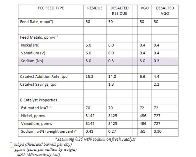
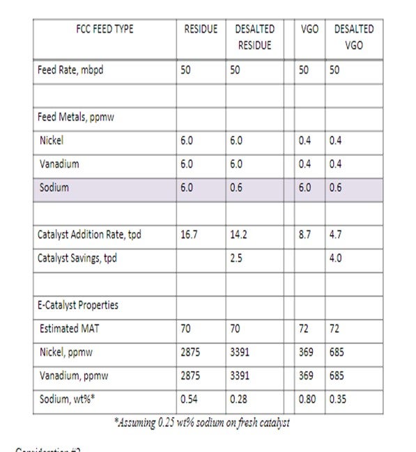
Another set of examples is included in the next table where the base sodium content of the feed is increased from 3 to 6 ppmw. In these examples, the VGO operation still shows a larger estimated reduction in FCC catalyst makeup for the desalted feed.
Consideration #2
Reduced crude which comes directly from crude desalting and distillation operations contains no free water but includes salt in crystalline form. Therefore, since imported feeds may have been previously desalted, makeupwater for FCC feed desalters should be installed as far upstream of the desalter as possible to give salt crystals the maximum opportunity to dissolve into the added water. (In crude desalters, a good portion of the salt in the raw crude is dispersed in the water produced with the native crude.) Plant operating experience has shown that salt dissolved in water is much easier to remove in the desalter than crystalline salt in the oil phase. Therefore, since imported feeds may have been previously desalted, makeupwater for FCC feed desalters should be installed as far upstream of the desalter as possible to give salt crystals the maximum opportunity to dissolve into the added water.
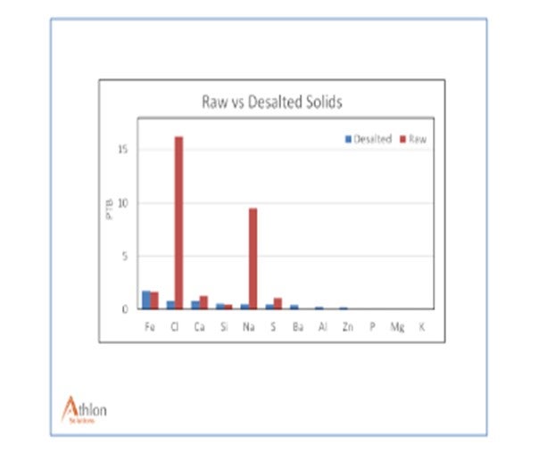
The two figures show the feed and effluent of a desalter processing imported LTO atmospheric residue filtered through 0.45-micron glass fiber filter paper and toluene rinsed. Based on salt levels, the feed was either not desalted, poorly desalted,or a purchased blend of desalted and non-desalted atmospheric residues.
Testing showed that the material on the filter paper was predominantly carbon, oxygen, sodium, chlorine, and iron. The testing was done with SEM/EDS (Scanning Electron Microscope/ Energy-Dispersive X-ray spectroscopy), which is unable to detecthydrogen.
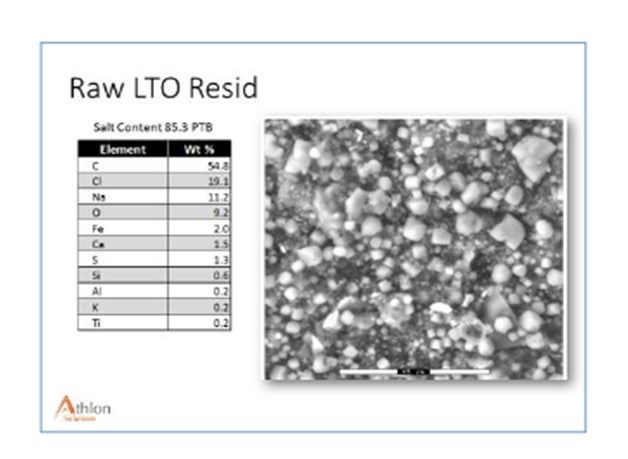
Slide Two shows the oil after desalting, caught at the same time as the raw oil in Slide One. The SEM image of filter paper showed significant NaCl, or salt, removal but very little impact on some of the other cations. Iron removal was insignificant from a total mass basis. A significant amount of iron was siderite rather than iron oxide or iron sulfide and was not easily removed with waterwashing. Phosphorus and barium are indicative of chemical treatment to prevent barium sulfate scale inhibition in formation.
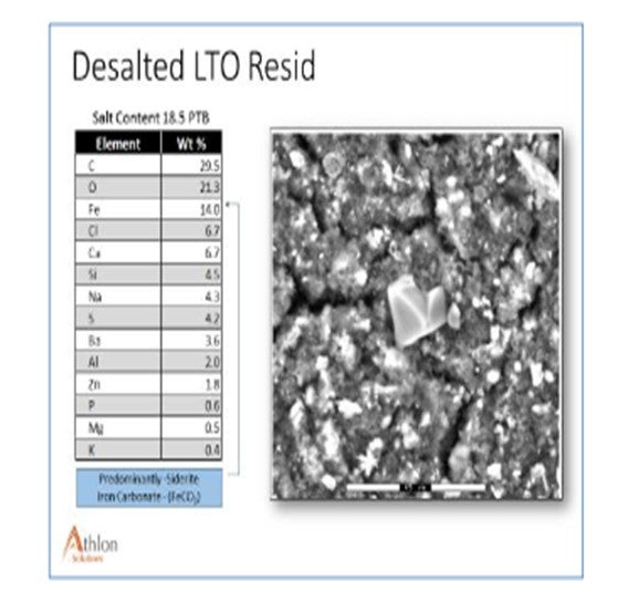
Slide 3 shows the estimated amount of each element removed in the desalter. The Na, Ca, Cl[sodium, calcium, and chloride], and some sulfates are readily removed. Iron and other metals are not removed as easily, and non-traditional techniques may be needed (pH adjustment).
Consideration #3:
Since reduced crude, topped crude, and even whole crude from paraffinic tight oils may be good candidates for FCC processing, some general considerations for desalting tight oils or other highly paraffinic crudes are also included in the references provided in the Answer Book. A few items of note are listed below:
*Common tight oil characteristics include high levels of very fine filterable solids and alkaline metals, calcium, sodium and magnesium.
*The solids loading can be as high as 300 pounds per 1000 barrels of crude.
*While traditional desalter chemical treatment programs focused on salt and water removal, the focus is now shifting to also encompass solids, particularly Iron removal efficiency.
*High desalter temperatures (up to 300°F) are needed with heavy feeds or waxy feeds to ensure low viscosities for full dehydration as well as the melting of all the asphaltenes and high molecular weight waxes that can encapsulate salt crystals.
*Acidification of the desalter water has been found to remove additional amounts of iron oxide and iron sulfide particles found in many crude oils, but acidification has not been as effective in removing the iron carbonates found in some light tight oils.
Year
2016
Process
Question 61: How many inside/outside operators staff your FCC plant? What other processes are included in their scope of responsibility?
ZACH BEZON
[United Refining Company (URC)] Our FCC unit has five operators per shift. Typically, two people are inside running the DCS (distributed control system) and board-mounted controls while the other three are doing rounds in the unit. Units included in the FCC are:
*FCC,
*Gas concentration unit,
*Polymerization unit,
*Alkylation unit (H2SO4) with a dedicated satellite control room in this unit,
*One boiler,
*Multiple cooling towers, and
*Gasoline treating unit.
Year
2016
Process