A New Approach for Effective Safety Training
Moderator:Willis Jernigan, Koch Companies Public Sector, LLC
Speakers
Session Start End
-


REYNOLDS (Phillips 66)
Phillips 66 has not done very much research towards iC5, specifically. We did review some base data and looked for some correlations with what impacts the iC5 production, and we did not find too many that are strongly correlated.
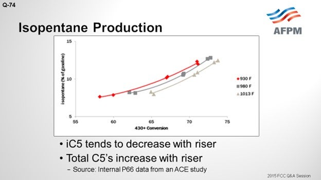
The riser does have an impact. On the Y axis, this plot shows the isopentane as a percentage of the gasoline; a 430°F+ conversion is shown on the X axis. There are three curves representing three different riser temperatures. There is a very wide range in these three risers: from 930 to 1013°F; but at constant conversion, the iC5 decreases with riser outlet temperature by about 1.5 wt% across that really wide range of riser temperatures. Across the conversion, there is a fairly significant change. So, as you crack more material into gasoline, the fraction of gasoline that is comprised of the total C5s will go up.
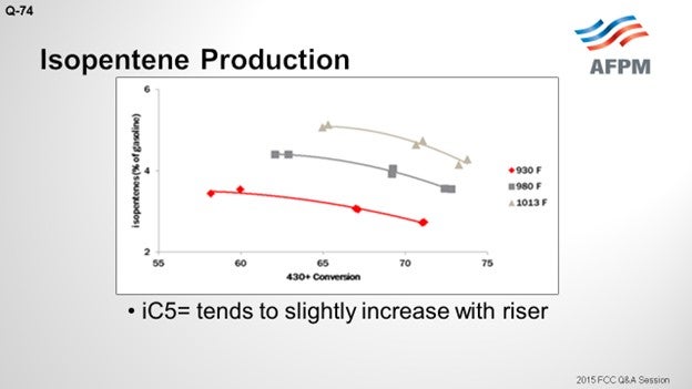
I included isopentene. The C5 olefins will be present along with the iC5s. They have a similar RVP (Reid vapor pressure). As opposed to iC5, C5 olefins increase with increased riser with a similar magnitude of change. So essentially, you are trading barrels of iC5 for C5 olefins, which has a negligible effect on RVP.
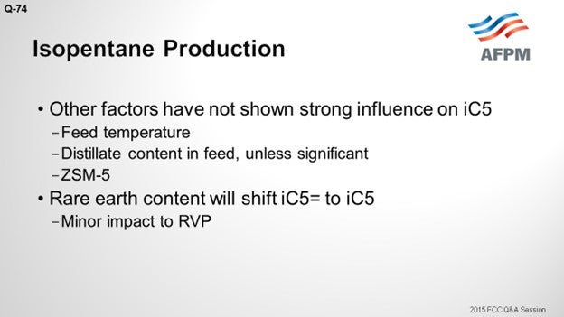
Other parameters we have reviewed which really do not seem to influence iC5 production are feed temperature and distillate content in the feed. You must have a significant change in distillate content; for example, a 40% change of your feed distillate will make about a 1% iC5 change. Unexpectedly, we did not see too much of a correlation with ZSM-5. You would think that if you crack the C6/C7 range of gasoline into LPG, you will have a concentrating effect; but we did not see that. Bart probably will disagree with me. Rare earth content will shift your olefins to your iC5 via hydrogen transfer reactions; but again, it will not have a huge impact on the RVP.
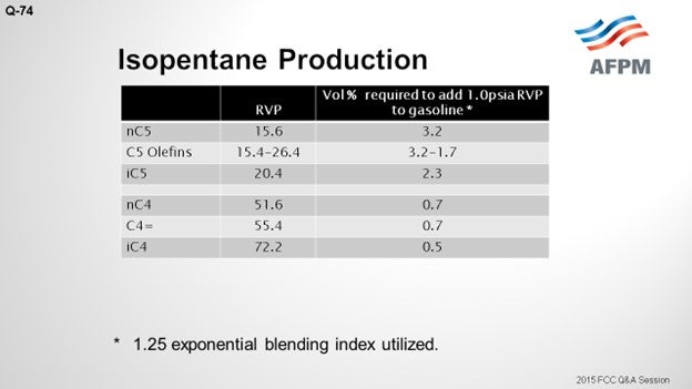
This table shows some of the RVPs for the C4- and C5-range materials. I included a column that indicates the volume percent required to add one psia (pounds per square inch absolute) of RVP to gasoline. You can see that there is a significantly larger impact from the butanes. So, when comparing normal butane to iC5, you can see that it has about four times the impact.
In conclusion, I think a facility must have an extremely high value of RVP barrels to warrant riser or catalyst formulation to make a negligible impact on iC5. I think your first priority is to try to get as much of the C4s out of your gasoline as you can. If you really do have C5s that are impacting your blending pool RVP, you should look at fractionating them out of gasoline into your C4 streams.
DE GRAAF (Johnson Matthey Process Technologies)
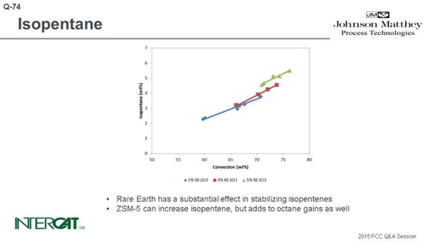
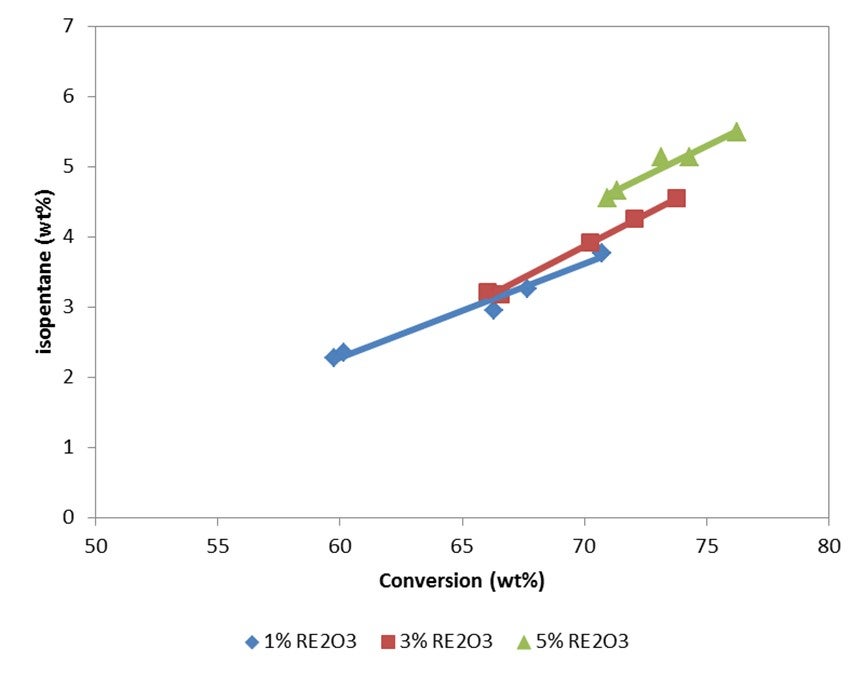
Isopentane is one of the lightest components in gasoline, and typically everything that increases conversion will increase isopentane. The rarer earth you have, the more hydrogen transfer of your catalyst, the more isopentane you will create. So, if you go for a higher riser outlet temperature, you will shift the equilibrium between isopentane and isopentene. A higher rise will give you more isopentane. Use of ZSM-5 additives can increase isopentanes because isopentenes can be transformed into isopentanes by hydrogen transfer. However, the effect of conversion is the most important factor affecting the amount of isopentane formed.
KENNETH BRYDEN (Grace Catalysts Technologies)
While the question asks specifically about isopentane production, other C5 hydrocarbons also have significant vapor pressure. Isopentane has a Reid Vapor Pressure (RVP) of 20 psi (pounds per square inch); n-pentane has an RVP of 16 psi; and, the C5 olefins have RVPs between 14 and 26 psi9. For refineries desiring to minimize RVP, it is also important to minimize the quantity of C4s in the gasoline pool since C4s have even higher vapor pressures than C5s.
Isopentane is mainly produced in the FCC unit via two pathways. The first pathway is cracking where isopentane is formed when a larger paraffin molecule cracks via β-scission to form isopentane and an olefin. The second main pathway for isopentane production involves hydrogen transfer reactions that transform C5 olefins into isopentane. Hydrogen transfer is a disproportionation reaction where hydrogen is moved between molecules. Isopentane production is influenced by operating conditions, feedstock properties, and the properties of the catalyst used. Factors that influence hydrogen transfer have the greatest impact on isopentane production.
As conversion is increased (by either increasing reactor temperature or by increasing catalyst-to-oil ratio), the quantity of isopentane (and gasoline) increases. At constant conversion, increasing reactor temperature will reduce the amount of isopentane produced, as hydrogen transfer tends to be favored at lower reactor temperatures. And since hydrogen transfer is a bimolecular reaction, decreasing reactor pressure lowers hydrogen transfer and will lower the amount of isopentane produced.
As a feedstock becomes more naphthenic, the production of isopentane tends to increase. This is because naphthenes are good hydrogen donors and react with gasoline range olefins to make aromatics and gasoline range paraffins10.
FCC catalyst can affect the rate of isopentane production through hydrogen transfer activity. As hydrogen transfer increases, more paraffins are formed and isopentane production increases. Figure 1(a) presents isopentane yields on a fresh feed basis at 72% conversion for a series of catalysts with a range of unit cell sizes (UCS) between 24.22 and 24.44 Å. To maintain similar activity, the higher UCS catalysts were formulated to a lower zeolite level. Figure 1(b) presents isopentane concentration in gasoline as a function of UCS for the same catalysts. As expected, isopentane yield and concentration in gasoline increase with UCS since the acid site density and the relative rate of hydrogen transfer to cracking is increasing.
The use of ZSM-5 based additives does not significantly change the yield of isopentane on a fresh feed basis, but it will increase the relative concentration of isopentane in the gasoline. As the higher olefins in gasoline are cracked by the ZSM-5 to propylene and butylene, the gasoline becomes enriched in isopentane. Figure 2(a) presents isopentane yield on a fresh feed basis for a series of ZSM-5 additive levels. While there is a slight increase in isopentane yield with ZSM-5 additive level, the isopentane yields are all close together. Figure 2(b) presents isopentane concentration in gasoline for the same series of ZSM-5 additive levels. As seen in the figure, isopentane concentration in gasoline increases with increasing ZSM-5 additive level.
In summary, a number of factors influence isopentane production, including feedstock, unit operating conditions, and the properties of the catalyst system used. Refiners desiring to reduce gasoline RVP should look at more than just isopentane since other C4s and C5s also contribute to vapor pressure. If catalyst changes are envisioned to minimize RVP, it is important to remember that 1) multiple objectives must be met in FCC operation and 2) careful consideration of operating objectives and unit constraints is needed when selecting a catalyst. Grace’s Technical Service team can help identify the best catalyst choice to meet refinery objectives.
BART DE GRAAF (Johnson Matthey Process Technologies)
Isopentane is one of the lightest components in gasoline. Typically, everything that increases conversion increases isopentane production. Isopentanes are formed from isopentenes via hydrogen transfer. Hydrogen transfer is a fast reaction under FCC conditions. High concentrations of zeolite in catalyst, and especially high rare earth stabilized USY, favor the formation of isopentanes. With riser outlet temperature, iC5 production increases, but mostly of the olefinic species. ZSM-5 additives can create isopentenes, which will form isopentanes after hydrogen transfer.
SINGH (Indian Oil Corporation Limited)
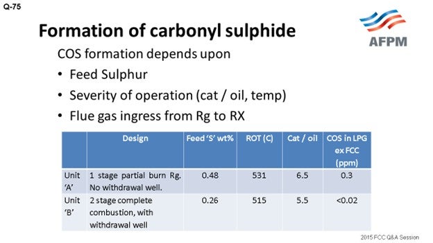
Carbonyl sulfide is produced during the cracking reaction and boils slightly below propane at -50°C (-58°F). Upon post-fractionation, it concentrates predominantly in propylene. COS (carbonyl sulfide) level in FCC LPG most strongly corresponds to the sulfur in the feed. The amount usually rises with increased feed sulfur but is unpredictable. Typically, every 0.6 wt% in feed sulfur corresponds to nearly 7 to 8 ppm in COS in LPG. The exact path by which COS is formed in the riser is not very clear, but formation of COS involves CO and CO2. This formation predominantly depends on feed sulfur, severity of cracking, reaction temperature, and flue gas ingress from the regenerator (Rg) to the reactor (Rx).
In the units maximizing the yield of propylene, formation of COS is lower if propylene maximization is achieved by the addition of ZSM5 rather than by increasing reaction severity. Sulfur in the feed is the biggest contributor to COS formation, the concentration of H2S being directly proportional to sulfur in the feed. There is an option for reduction of COS formation by pretreatment of feed to minimize the feed sulfur content. COS formation is pronounced in partial combustion regenerators; hence, a full-burn regenerator may be a choice if the objective is COS reduction.
In Indian Oil, we are operating FCC units of different designs and configurations: partial-burn, full-burn, single and double regenerators, with and without a withdrawal well. I have tried to compare the data of two units of different designs. Unit A is a single-stage, partial-burn regenerator with no withdrawal well, while Unit B is a two-stage regenerator with complete combustion and a withdrawal well. The feed sulfur corresponding to Unit A is 0.48; the feed sulfur is 0.26 in Unit B.
Though it is difficult to directly correlate, as per our experience in the units with built-in design for complete combustion and with the withdrawal well (which provides defluidization of regenerated catalyst before it enters the riser), COS formation is less. Traditional treating with caustic solution is not very effective for removing COS from the hydrocarbon stream to very low levels. It can be removed by hydrolysis or the adsorption method. The COS hydrolyzer reactor converts COS to H2S, which is typically easily captured by caustic. COS, in traces, can be removed by guard beds of aluminum-based selective adsorbents.
DE GRAAF (Johnson Matthey Process Technologies)
COS contamination in propylene is a problem because small quantities can already make it suspect of polymer grades. COS is formed in the regenerator, but this can be carried over into the pores of the catalyst into the riser. And in the riser, the COS can react readily with water vapor to form H2S. Theoretically, it is possible to form COS from the reaction of H2S and CO. But if this reaction would take place, it is probably at a negligible phase. When you are studying how much COS can be present in the propylene, you see that a wide span of values can be present, revealing that there is probably not so much of a chemical catalytic effect as an operational effect.
COS is a light boiling component; but if it ends up in the LPG, it has a lighter boiling point than propylene and propane. So, any COS that is still present in the LPG will end up in the propylene stream. If you have any change in the amount of LPG you make, you will probably have to pay a lot of attention to the split between LPG and dry gas, because any dry gas and COS that can slip into the LPG will end up in the propylene stream. So, for example, when you start using ZSM-5 additives or increase conversion in your unit, detailed monitoring of your LPG and dry gas splits probably will help prevent a lot of COS from ending up in your propylene.
YORKLIN YANG (BASF Corporation)
COS is a species formed in the FCC due to a number of reactions between CO, CO2, coke, water, sulfur, hydrogen sulfide, and possibly other compounds. COS fractionates out in the propylene (C3=) stream in FCC gas plants and often causes corrosion problems in LPG. Carbonyl sulfide inhibits selective hydrotreating and the activity of gasoline hydrotreating. Polymer-grade propylene product specification for COS is often in the ppb (parts per billion) range. In the recovery section, the majority of the carbonyl sulfide fractionates out with the propylene product.
Industry experts believe that COS forms in equilibrium with the materials in the riser. It is believed that the key to minimizing the formation of COS is to minimize the undercarry of regenerator flue gas with the regenerated catalyst. Partial-burn units typically have more problems with COS than full-combustion units. In practice, COS minimization could be done by using a gas other than air for regenerated catalyst standpipe aeration, as well as by having a proper hopper to degas the regenerated catalyst before it enters the standpipe. Any free H2S entering the riser is also a known COS producer.
Bart just made some very good comments. I have a couple of experiences related to this question. Most cases are related to high severity FCC which are run with a much higher riser outlet temperature for making a polymer-grade propylene product, and COS is really the main issue. One example is that it is common to use dry air for regenerated standpipe aeration. If we could switch to nitrogen or steam for standpipe aeration, that would reduce at least 20 to 50% of COS formation.
Another suggestion Sanjiv mentioned is that if you have a catalyst withdrawal well, the flue gas will be entrained with catalyst. However, the purge gas for the catalyst well could be switched to use nitrogen or steam instead of air, tremendously reducing the amount of COS.
In the FCC treatment system, COS may be removed by adsorption on a catalyst bed or with an amine (MEA or DEA) system. Approximately 80% of the COS is hydrolyzed in the amine unit where it reacts as carbon dioxide and hydrogen sulfide. The remaining 20% forms amine stable salts. For a lower COS content inlet, like 1 ppmw (parts per million by weight), it will be more economical to install a molecular sieve reactor bed than an amine system. At some point, the economics tip toward an amine system when the concentration of COS in the FCC off gas is high enough to require a reactor bed which has a size and equivalent capital and operating expense that exceeds the cost of the equipment and operation of an amine system.
ROBERT (BOB) LUDOLPH [Shell Global Solutions (US), Inc.]
I want to share an experience with a full-burn FCC that I had some years ago. The unit had a serious catalyst loss problem. The refinery chose to import e-cat to make up for the losses. The e-cat also contained SOx reduction additive, an additive that the operator of the full-burn FCC had not been adding previously. Coincidentally, it was observed that the COS content of the PP (propane propylene) increased after the e-cat was added to the inventory. The gas plant included a deethanizer which was later operated differently to manage the COS but resulted in a loss of propylene to the fuel gas system. The combination of the e-cat (containing the SOx reduction additive) with the unit inventory catalyst led to a COS issue that was unexpected. The additive was the suspected cause but could not be proven. So just a warning: If you are going to import e-cat for makeup, review the properties carefully and understand what catalyst additives might be present. Identify any risks and lay out the actions for remediation.
EMERSON FRY (Delek Refining, Ltd.)
Those are excellent suggestions. I will simply add that a KOH (potassium hydroxide) bed can also be effective in removing COS or at least keeping it dry enough to prevent it from hydrolyzing to H2S.
BART DE GRAAF (Johnson Matthey Process Technologies)
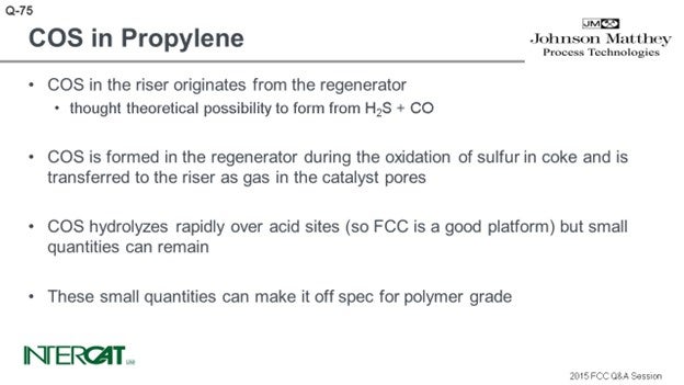
COS contamination in propylene is a problem as small quantities can make it off spec for polymer grade. COS in FCC products is typically formed in the regenerator. COS is formed in the regenerator during the oxidation of sulfur in coke and is transferred to the riser as gas in the catalyst pores. COS is very unstable in the presence of steam; it readily hydrolyzes over acid sites into H2S. Theoretically, it is possible to form COS from the reaction of H2S with CO over acid sites, though this reaction, if it takes place, is probably negligible in the riser.
Concentrations of COS in propylene streams vary over various orders of magnitude, which is unlikely to be a chemical effect only. Chemical composition of feeds and catalysts in FCC units show a smaller span in variation than COS in propylene. COS concentrations in propylene are a function of the efficiency in the split between fuel gas and LPG. Any COS that has not been removed from LPG will effectively end up in the propylene stream, as propylene is the lightest boiling component in LPG (see table). Therefore, with every change in wet gas production, the gas plant requires careful monitoring to minimize COS concentrations in propylene.
|
|
Boiling Point |
|
COS |
-58.4°F (-50.2°C) |
|
Propylene |
-53.7°F (-47.6°C) |
|
Propane |
-44.2°F (-42.2°C) |
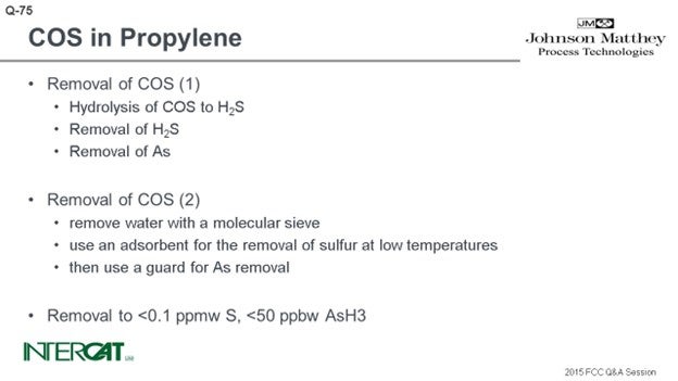
For the removal of COS there are two main basic routes. In the first, COS is hydrolyzed to H2S over an acidic catalyst. H2S is removed from the stream with polishing adsorbents. Thereafter, any as (arsenic) species are trapped in a guard bed. In the second route, water is removed from the gas stream with a molecular sieve. Thereafter an adsorbent is used for sulfur removal at low temperatures, and a guard bed is used for as removal. Removal efficiencies with either route is up to less than 0.1 ppmw (parts per million by weight) S, and less than 50 ppbw (parts per billion by weight) AsH3 (arsine) in the product.
SANJIV SINGH [Indian Oil Corp Ltd. (IOCL)]
Carbonyl sulfide (COS) is produced during the cracking reaction. It boils slightly below propane at minus 50°C (-58°F). Upon post-fractionation, the COS concentrates in the LPG, propane-propylene, and finally in propylene as the distilled cuts narrow in boiling range. COS concentrations in the LPG stream may range from 5 to 100 ppm. The COS level in FCC LPG most strongly corresponds to sulfur in the feed. The amount usually rises with increased feed sulfur but is very unpredictable. Typically, every 0.6 wt% sulfur in the feed corresponds to 7 to 8 ppmw COS in the debutanizer overhead liquid.
The exact path in which COS forms in the riser is not clear. A few possibilities are:
H2S + CO2 è COS + H2O
2CO + 2S è 2 COS
3 FeS2 + 4 CO2 + 2 CO è Fe3O4 + 6COS
SO2 + 3 CO è COS + 2 CO2
The formation of COS predominantly depends on the following,
Feed sulfur,
The severity of cracking (cat/oil ratio and temperature), and
Flue gas ingression to riser.
In the case of units maximizing the yield of propylene, the formation of COS will be lower if it is achieved by the addition of ZSM-5-based additive rather than the case with higher reaction severity.
Sulfur (S) in the feed is the biggest contributor to COS formation. The concentration of H2S will be directly proportional to S in the feed. The option for reduction of COS formation is pretreatment of feed to minimize the sulfur content. In our experience, COS formation is pronounced in partial-burn regenerators. Hence, full-burn regeneration may be an important consideration to minimize COS formation, especially in high propylene FCC units, due to stringent COS specification in propylene product. Some polymerization catalysts are sensitive to as little as 5 ppb COS. In an operating FCC unit, COS produced in the riser can predominantly be controlled by controlling feed sulfur.
IOCL operates FCC/RFCC units of different designs and configurations, e.g., partial- and full-combustion regenerators, with and without withdrawal well, single- and double-stage regeneration, etc. To assess the impact of parameters (other than feed sulfur) on the COS content in FCC LPG, the actual data of two units is compared below.
|
|
Design |
Feed ‘S’ wt% |
ROT* (°C) |
Cat/oil |
COS in LPG ex FCC (ppm) |
|
Unit A |
1-stage partial-burn regenerator, no withdrawal well |
0.42 0.48 0.67 |
531 |
6.5 |
0.15 0.30 0.35 |
|
Unit B |
2-stage complete combustion, with withdrawal well |
0.26 0.49 0.66 0.77 0.80 |
515 |
5.5 |
<0.02 <0.02 <0.02 <0.02 <0.02 |
* ROT (reactor outlet temperature)
Though it is difficult to directly correlate, our operating experience has clearly indicated that the units with a built-in design for complete combustion and defluidizing regenerated catalyst, by way of incorporating withdrawal well and reducing flue gas carryover from the regenerator to the reactor, are likely to have significantly lower COS formation.
The traditional method of treating with caustic or amine solution is not effective in removing COS from a hydrocarbon stream. COS can be removed by hydrolysis or adsorption methods.
There are several catalysts available for hydrolysis of COS into H2S and CO2. The COS hydrolysis reactor, located upstream of the caustic treater, converts COS to H2S, which is then easily captured by the caustic. COS in traces can be removed by guard beds consisting of alumina-based selective adsorbents. Some of the COS is hydrolyzed in the amine absorber (down to about 10 ppmw). If COS levels in the C3 product are desired to be less than 1 ppmw, there is usually an amine settler downstream. The amine settler uses the MEA+NaOH (monoethanolamine plus sodium hydroxide) solution to drive the hydrolysis of the remaining COS down to 1 ppmw or less. The C3 stream then goes to an adsorbent bed to remove the remaining COS.
NIKOLAS LARSEN [Marathon Petroleum Company (MPC)]
Several impurities are expected in a refinery propylene stream including carbonyl sulfide (COS), carbon disulfide (CS2), hydrogen sulfide (H2S), mercaptans (RSH), and arsine (AsH3). Removal of these contaminants is often required for reasons of safety, corrosion, and product specifications; to prevent poisoning of downstream catalysts; and, to meet environmental requirements. In one MPC unit, the treatment and/or removal of these impurities is accomplished through chemical reactions taking place in hydrolysis reactors, a propylene scrubber, and an arsine treater.
Hydrolysis Reactor and Propylene Scrubber Chemistry: The sulfur impurities that are present must be removed to meet product specifications. The spec for COS in this unit that produces polymer grade propylene is 40 ppbv (parts per billion by volume). Optimal water concentration for the hydrolysis reaction is two to three times the molar concentration of COS in the feed. In the unlikely event that the feed water content is less than optimal, hydrolysis reaction water can usually be injected upstream. The hydrolysis reactor catalyst promotes the hydrolysis of COS – and, to a lesser extent, CS2 – to carbon dioxide and hydrogen sulfide through the reactions shown below:
COS + H2O à CO2 + H2S (1)
CS2 + 2 H2O à CO2 + 2 H2S (2)
The products of reactions (1) and (2), being contaminants themselves, require removal. A 25 Baume (Be) caustic solution is injected downstream of the hydrolysis reactors, and mixing of the two streams occurs in a downstream static mixer. The caustic reacts with CO2, H2S, and mercaptans, as shown in the reactions below:
CO2 + 2 NaOH à Na2CO3 + H2O (3)
H2S + 2 NaOH à Na2S + 2 H2O (4)
RSH + NaOH à RSNa + H2O (5)
The products of reactions (3) through (5) are water-soluble rather than hydrocarbon-soluble; thus, they are contained in the spent caustic phase at the bottom section of the propylene scrubber. The caustic phase is recirculated through the mixer until spent. At this time, the spent caustic is drained, and fresh caustic is reintroduced to the system. Any entrained caustic in the process line leaving the scrubber can be removed by a downstream sand filter.
Arsine Treater Chemistry: Although only trace amounts of arsine are expected in a refinery propylene stream, enough is present to cause increased polymerization catalyst consumption resulting in decreased polymer quality in a downstream polymer unit. Arsine treater catalyst in this unit is composed of copper oxide, aluminum oxide, and aluminum silicate. The arsenic reacts primarily with the copper oxide in the reaction below:
AsH3 + 3 CuO à Cu3As2 + 3 H2O (6)
The arsine treater catalyst is also effective in the removal of sulfur containing impurities such as COS, H2S, CS2, and mercaptans (RSH) which may still remain in the hydrocarbon stream. These compounds primarily react with the copper oxide (CuO) as shown below:
COS + CuO à CuS + CO2 (7)
H2S + CuO à CuS + H2O (8)
RSH + CuO à CuS + ROH (9)
CS2 + 2 CuO à 2 CuS + CO2 (10