
Question 74: Please discuss how yield data can be used to identify hardware issues. What hardware issues can you address to fix dry gas and benzene production?
Alec Klinghoffer (Coffeyville Resources)
There are several examples of how yield data can be used to identify hardware issues in the FCCU. For example, a decrease in cat to oil and/or catalyst circulation (which leads to a decrease in overall conversion and liquid yield) can be the result of a high regenerator dense bed temperature at constant process conditions. Several mechanical/hardware issues can contribute to higher regenerator temperatures. For example, higher regenerator bed temperatures can be the result of inefficient catalyst stripping and/or internal stripper damage. Entrained hydrocarbons are not sufficiently stripped and are burned in the regenerator causing an increase in bed temperature. Another mathematical check to this would be the H2 on coke calculation. Higher regenerator bed temperatures can also be caused by poor feed atomization and feed nozzle damage. The gas oil is not properly atomized and is “stuck” to the catalyst, causing a higher regenerator bed temperature as it is burned. This also causes a decrease in liquid yield and increased dry gas make. Another example of where yield data can be used to identify hardware issues is in the reactor. A decrease in gasoline yield and an increase in dry gas make could indicate an issue with reactor cyclones. If there is a hole in the reactor cyclones or reactor cyclone performance has decreased, catalyst can be trapped in the disengaging section of the reactor and re-react with the vapors, causing an “overcracking” of gasoline which leads to an increased dry gas make and lower gasoline yield.
Though not truly yield data, increased regenerator emissions (NOx, SOx) can be indicative of regenerator air grid pluggage or damage. This leads to poor air and catalyst distribution in the regenerator and decreased catalyst additive performance.
Here is a brief list of hardware issues to address to minimize dry gas make:
1.Catalyst stripper
a.Stripping steam nozzles plugged?
b.Stripper internal damaged or stripper upgrades needed because of higher catalyst flux rate limited?
2.Feed nozzles
a.Feed nozzles plugged, or feed not properly atomized because of feed nozzle design and limitations?
3.Reactor Cyclones
a.Holes in the cyclones or cyclones not designed for increased loading
b. “Overcracking” in the dilute phase causing an increase in dry gas.
Benzene production in FCC gasoline is influenced by catalyst choice, contact time and reaction severity. To reduce benzene, one could shorten the contact time in the riser and reactor dilute phase. Changing the feed location in the riser would shorten riser contact time and minimizing reactor dilute phase cracking would also reduce the benzene in CAT gasoline.
Year
2010
Process
Question 75: What have refiners done to mitigate or eliminate coke buildup in reactors? How do you monitor and vary feed quality, reactor severity, catalyst formulation and other variables to impact coke formation. How does feed distributor operation and design impact reactor coke buildup?
Emerson Domingo (Sunoco)
A lot of coke formation can occur during start-ups and shutdowns and upsets of the unit. During start-up, it is important to make sure that all the reactor internals are hot and at operating temperature before introducing oil. If the temperature is too low, the hydrocarbon will condense and form coke. It is also desirable to initially start-up during the first few hours without resid in the feed so there are less chances of heavy hydrocarbon condensing in cold spots.
Similarly, during a unit upset, feed needs to be pulled before the riser gets too cold. This is typically done at 900F. Once feed is pulled the riser and reactor should be completely purged with emergency riser steam so that the hydrocarbon is swept out of the system and pushed to the main fractionator.
It is also important to make sure that oil stays out of the riser by manually closing a main valve going to the feed nozzles. There have been instances when feed has been diverted at the proper temperature but by accident the feed is re-introduced into the riser without anyone knowing about it. This can be caused by valve misalignments or an automatic divert valve malfunction. Once feed is diverted, it is a good practice to close a manual block valve in the feed system. Don’t rely on the automatic divert system as it may get re-opened. During normal operation, maintain riser and reactor temperature well above minimum at all times to avoid condensation of hydrocarbons. It is very important that the oil is well atomized and mixed well with the catalyst in the feed injection zone. Monitor the performance of the feed nozzles to make sure you have the right DP across the feed nozzles. At the end of a major turnaround, you should physically check each feed nozzle to make sure they are clear. Go through the entire feed nozzle check procedure before oil-in to confirm that there are no plugged nozzles.
in the reactor, there should be dome steam purge just above the cyclones to prevent coke build-up outside the cyclones and in the reactor head. The steam used should be superheated and is normally controlled with an orifice plate to ensure adequate flow. One of our risers has a T-inertial separator with a “shotgun” at the top of the riser. The “shotgun” directs some of the riser effluent to the reactor dome area to keep it from being stagnant. This “shotgun” extension is in lieu of reactor dome steam. Also, the stripper section should be well designed so it allows for a net upflow of steam towards the reactor cyclones and keeps velocities up in the reactor and prevents dead space.
Year
2010
Process
Question 76: How can you tell if spent catalyst stripping is "good"? We don't believe our hydrogen on coke results
Steve Shimoda (SHAW)
In the Shaw RFCC, we utilize a withdrawal well design that allows the catalyst to deaerate before it enters the RCSP. The withdrawal well achieves a very high catalyst density at a stable flux. It can also help the pressure balance. Entrained inerts are defined by the following equation:
Entrained Gas Calculation:
ACFSgas = (ccr / ρsp) x (1 - ρsp / ρsk)
Where:
ccr = catalyst circulation rate, lb/s
ρsp = mixture density in standpipe, lb/cf
ρsk = catalyst skeletal density, lb/cf
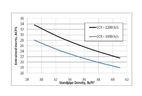
From the equation it’s easy to see that inerts can be minimized by reducing catalyst circulation rate or increasing the catalyst density in the standpipe. Reducing the catalyst circulation will linearly reduce the amount of inerts. Generally, this will not provide a good overall solution for the cat cracker. By adjusting the standpipe aeration, the density in the standpipe can be increased and the entrained inerts will decrease as shown in the following graph.

Another option to minimize inerts would be to displace them with steam. However, there will be a penalty of catalyst deactivation. The catalyst deactivation in the presence of steam is particularly noticeable at high regenerator temperatures and high metals on catalyst loading.
Year
2010
Process
Question 77: How do you minimize the entrainment of inerts from the regenerator which eventually enter the fuel gas system and sulfur recovery units reducing available capacity?
Steve Shimoda (SHAW)
In the Shaw RFCC, we utilize a withdrawal well design that allows the catalyst to deaerate before it enters the RCSP. The withdrawal well achieves a very high catalyst density at a stable flux. It can also help the pressure balance. Entrained inerts are defined by the following equation:
Entrained Gas Calculation:
ACFSgas = (ccr / ρsp) x (1 - ρsp / ρsk)
Where:
ccr = catalyst circulation rate, lb/s
ρsp = mixture density in standpipe, lb/cf
ρsk = catalyst skeletal density, lb/cf
From the equation it’s easy to see that inerts can be minimized by reducing catalyst circulation rate or increasing the catalyst density in the standpipe. Reducing the catalyst circulation will linearly reduce the amount of inerts. Generally, this will not provide a good overall solution for the cat cracker. By adjusting the standpipe aeration, the density in the standpipe can be increased and the entrained inerts will decrease as shown in the following graph.
Another option to minimize inerts would be to displace them with steam. However, there will be a penalty of catalyst deactivation. The catalyst deactivation in the presence of steam is particularly noticeable at high regenerator temperatures and high metals on catalyst loading.
Year
2010
Process
Question 78: In your experience, how effective and reliable are hydrocyclones, electrostatic separator, additives, and filters in reducing the ash content of the slurry?
Alec Klinghoffer (Coffeyville Resources)
There are basically 3 types of ways to reduce the ash content in slurry oil. They are electrostatic separators, additives with settling and filters. They all have their advantages and disadvantages, and they all do a reasonable job in reducing ash in slurry. I personally do not know of any refinery that uses hydrocyclones to remove ash from slurry oil. There are two major licensors of filters, Mott and pall. Mott uses its HyPulse® LSI filters, which are back washable metal filters that contain tubular porous metal elements installed in a tubesheet at the bottom of a vessel. Feed slurry is introduced to the filter below the tube sheet and flows through the inside of the filter elements. Solids collect on the inside surface of the elements as filtrate passes through to elements to the outside surface. Accumulation of solids in the filter elements is followed by back flush to remove the solids as highly concentrated slurry. Mott claims in excess of 99.8% efficiency and several refineries have reported run lengths of close to 10 years without any significant issues. The literature suggests most of their installations are outside the United States. A very few, select refineries still use the Gulftronic separator. The separator is analogous to an ESP on the regenerator flue gas where an electrostatic field is used to remove particles from the slurry. The Gulftronic unit uses a clean and backwash cycle. In the clean cycle, the glass beads become ionized in an electrostatic field. A depletion zone is created because of a loss of ions on the surface of the beads. In the backwash cycle, the beads are fluidized, causing them to rub against each other and releasing the catalyst particles. In both applications, the stream with a high density of catalyst fines is recycled back to the riser. One independent refiner in the southwest US uses this to produce a slurry that is sold directly to a carbon black plant, and they report very few issues with the Gulftronic separator. A larger portion of US refineries either modify equipment to minimize catalyst losses in the slurry or they use a combination of additives and settling to separate particles from the slurry oil. Additives work by changing the electronic surface structure of the catalyst particle and allowing better particle agglomeration of the particle, so the particles become heavier and settle out of the slurry. For the most part, this tends to work in a wide range of applications and operating regimes, but Coffeyville has recently experienced a situation where additives did not have a significant impact in decreasing the ash content of slurry oil.
Year
2010
Process
Question 79: Backwash containing catalyst fines collected by main column bottoms hydrocyclones, filters or electrostatic precipitators are normally routed back to the FCC reactor riser. In your experience, how does the recycle of catalyst fines in main column bottoms impact particulate emissions from the FCCU?
Jill Brown Burns (Sulzer Chemtech USA)
The distribution of pumparound duties in the Main Fractionator dictates the amount of LCO recovery from the bottom's product. The primary handle to adjust LCO production is the pumparound duty below the LCO section (slurry pumparound or slurry and HCO pumparounds in towers with an HCO section), not the LCO pumparound. When the pumparound duty below the LCO section is reduced, more LCO-ranged material travels up the column, which will increase the LCO section temperature. The LCO product rate and endpoint will both increase.
Often increasing tower traffic by reducing the lower pumparounds may create hydraulic restrictions further up in the column. The refiner may observe high tower pressure drops or a lack of appropriate separation response to a duty adjustment that may indicate flooding in a Main Fractionator with insufficient capacity to handle the increased traffic. The column internals should then be evaluated for replacement with high-capacity tray designs or packing.
Often the management of LCO recovery competes with FCC feed preheat targets due to the slurry pumparound exchanging heat with the incoming gas oil feed. The preheat temperature impacts FCC reactor heat balance and yields and is typically a less flexible target than LCO recovery. For units without an HCO pumparound, there is then very limited ability to control LCO recovery. The refiner may consider the addition of a fired feed preheater to create more flexibility in the system and to decouple the feed preheat objective from LCO endpoint control.
Another problem encountered while trying to maximize LCO recovery is coking above the slurry pumparound. Large reductions in slurry pumparound duty without a corresponding increase in HCO pumparound duty can result in high temperatures in the section immediately above the slurry pumparound return. Additionally, should the refiner choose to adjust the duty by manipulating the pumparound flow, a minimum flow rate can be reached on the return distributor. Poor distribution increases the risk of coking in the slurry packing, which can then force high vapor rates and poor vapor distribution from the remaining unrestricted portion of the bed, resulting in entrainment of high endpoint material into the HCO section.
A similar consequence can actually be observed when the slurry pumparound duty is increased too much. Sufficient distillate must be allowed to travel up out of the slurry section to condense and wash back down keeping the lowest tray or zone of packing fully wetted. This area in the tower can also be subject to coking should that amount of distillate be too low.
Year
2010
Process
Question 80: What best practices do you recommend to improve LCO recovery? Do changes in LCO pump around affect LCO recovery? What are common challenges?
Alec Klinghoffer (Coffeyville Resources)
There has been a lot of work and discussion on LCO maximization at the FCCU and there is plenty of literature on different options for LCO recovery. This will be a general overview of available options to refiners and some challenges recently experienced at Coffeyville. There are four main categories for LCO maximization. They are:
1.Feedstock optimization
2.Catalyst optimization/ changes
3.Operating Conditions
4.Main fractionator optimization/adjustments
Feedstock optimization includes feed hydrotreating optimization, residual feedstock optimization, and removal of diesel range material from the FCC feed. There will be very little discussion about this since Coffeyville runs non-hydrotreated CAT feed and there is very little ability to optimize the feed quality. Catalyst optimization and/or catalyst changes are a longer-term solution and are generally used and effective if the long-term refinery strategy is to maximize LCO in the cat cracker. These optimization strategies include increased bottoms conversion using a higher matrix surface area catalyst, targeting a lower fresh catalyst activity (which includes lower zeolite activity catalyst) and any other catalyst changes that suppress catalyst activity. Again, each catalyst vendor has its own technology for upgrading bottoms conversion without producing more gasoline and LPG. Operating conditions can be adjusted to lower activity and selectively maximize LCO. These include operating at a lower riser temperature, and increasing the feed preheat temperature. Directionally these moves decrease cat to oil and catalyst circulation and tend to shift yields to LCO. In addition, equilibrium catalyst can be lowered to preferentially lower conversion and selective make more LCO. Finally, main fractionator adjustments and optimization are an easy and effective method to increase LCO yield. Coffeyville has experience in these because these moves are also used to mitigate other FCC limits. For example, one can lower the gasoline 90 and push the heavy end of the gasoline range material into the LCO. Additionally, main fractionator bottoms stripping steam and temperature can be increased to push the light end of the slurry into the LCO. LCO pumparound would have an effect in that lowering the pumparound would allow heavier material up the tower and could be captured as increased LCO. Fractionation moves are probably the easiest and can be used to take advantage of short-term opportunities based on favorable LCO economics. Some of the pitfalls are issues of LCO quality. One has to make sure the cloud point and/or LCO endpoint does not significantly increase to cause blending issues. In addition, by adding lighter material to the LCO, one has to watch the flash point on the LCO rundown steam. Bottoms recycle can also be used to increase LCO yield but here is a penalty associated with overlap liquid yield.
Year
2010
Process

Sonya T. Proctor
Assistant Administrator for Surface Operations, TSA
U.S. Department of Homeland Security
Question 81: Refiners operating FCCUs producing high levels of propylene have seen different or excessive product contaminants when compared to a less severe operation. In your experience, how has this impacted gasoline or LPG treating unit? What specific contaminants have you identified? What impact have you seen in amine color, consumption, or foaming tendency? What actions have you taken that have mitigated or prevented treating unit issues?
Steve Shimoda (SHAW)
The answer to this question depends on what is considered high levels of propylene and what is the method to achieve it. If the additional propylene is produced by the addition of ZSM-5 to a standard operation, then I would not expect to see additional effects of contaminants. However, if the propylene production is increased through higher severity, ROT, bottoms cracking, etc., then there will be additional contaminant issues.
At Shaw, we have had several recent designs with the goal to maximize production of propylene. The highest level of polymer grade propylene (PGP) is achieved using the Shaw DCC process. This process uses high reactor temperature & post-riser bed cracking to complete conversion of naphtha to LPG. Selectivity is maintained by minimizing hydrocarbon partial pressure.
Butadiene contamination may be more pronounced at the higher reaction severity. Special attention to reboiler design is important in mitigating issues of reboiler fouling. Note that downstream C4 Alkylation feed may contain oxygenates such as acetone as well as higher butadienes.
Impact on gasoline treating
Hydrotreated feed gives low RSH in gasoline. Di-olefins are slightly higher but can be handled using standard antioxidant chemical injection. Special attention to reboiler design is important in mitigating issues of reboiler fouling. Note DCC technology includes non-HT feeds as well. Several DCC units have operated more than 12 years on non-hydrotreated feedstocks, using only chemical additives to suppress gum formation.
Impact on LPG treating
There are no particular issues in LPG treating. Standard amines have been successful in over 12 years on DCC operation. There is no foaming or degradation of amine, requiring special attention. Note that normal operating procedures keep the amine clean by filtering and carbon adsorption. Reasonable acid gas loadings on the rich amine prevent corrosion in the system. In the referenced DCC unit, DEA was used as the amine, since CO2 rejection was important to off gas treating for ethylene recovery.
RSH extraction from LPG by regenerable caustic has also been successful in 12+ year’s operation.
Other specific contaminants include methanol and acetaldehyde. Trace methanol is easily removed from C3 stream using a regenerable adsorbent bed. Note that some crudes contain trace arsine or mercury. These can be removed with non-regenerable adsorbent beds.
Year
2010
Process