Question 34: What solutions do you have for extending cycle length in distillate hydrotreating units limited by product color?
Year
2014
Process
William Diggins and Robert Dolejs (UOP)
As far as Inspection techniques and methods, the following should be employed. Application of these would be based on customer’s inspection plan and/or Risk Based Inspection (RBI). Other things that would trigger examination would be thermal excursions or checking for in service cracking after 15 years. Reactors built before 1990 did not have the pedigree materials of reactors built after 1990 and should be subjected to volumetric weld seam examinations more frequently. Since this is done on the outside of the vessel it can be done during turnarounds and/or catalyst change outs.
1.Visual inspection
2.Hammer testing weld overlay/cladding for disbonding. Straight beam scans of areas for disbonding can be done, but hammer testing is cheaper and faster.
3.Thickness survey to satisfy API-510 requirements
4.Halogen free liquid penetrant materials – random inspection of weld overlay and ring joint grooves for cracking. Minimum dwell time for weld overlay should not be less than 30 minutes. Eddy current techniques may be employed, but UOP does not at this time have direct experience with this technique.
5.Wet magnetic particle examination technique using an AC yoke to check external nozzle welds for cracking
6.External volumetric ultrasonic angle beam examinations to check for in service cracking of weld seams and bottom head/skirt weld. Using laser technology to check inside diameter reactor for bulging.
Mark Mucek (UOP)
Specific to hydroprocessing units, chloride stress corrosion cracking (Cl SCC) is really only an issue on the outside of piping and equipment. During normal operation the process side of units that have austenitic stainless steel operate too hot for liquid water to be present; a requirement for Cl SCC to occur. Chlorides can get to the outside of austenitic stainless steel in one of two ways; either leaching out of the insulation, or from a sea-coast atmosphere. Addressing the former, UOP specifies that thermal insulation to be used in contact with austenitic stainless steel be in accordance with ASTM C795, Standard Specification for Thermal Insulation in Contact with Austenitic Stainless Steel. This specification has two major requirements; (1) conduct a stress corrosion cracking test in accordance with ASTM C692, and (2) conduct chemical analyses in accordance with ASTM C871, and report levels of chloride, fluoride, sodium and silicate. pH must be ≤ 12.5. As for chlorides from a sea-coast atmosphere, UOP does not provide specific direction as this is addressed on a case-by-case basis. One Gulf Coast refiner used a high-temperature paint on the austenitic stainless-steel piping in their hydrocracking unit, however, whether this has been successful is not known. Also, this approach is not common.
With regard to Polythionic acid stress corrosion cracking (PTA SCC), UOP directs its customers to NACE Standard Practice SP0170, Protection of Austenitic Stainless Steels and Other Austenitic Alloys from Polythionic Acid Stress Corrosion Cracking During Shutdown of Refinery Equipment. For PTA SCC to occur, five conditions must be met simultaneously. These are: (1) a sensitized microstructure, (2) a metal sulfide scale on the surface, (3) stress (either residual or applied), (4) liquid water, and (5) oxygen. Remove any one of these five conditions and PTA SCC cannot occur. Due to the nature of the process, asensitized microstructure and a metal sulfide scale on the surface can never be eliminated. Stress also cannot be eliminated since residual stress is enough to drive PTA SCC. In some cases liquid water can be eliminated. For example, a pilot burner in a fired heater can be lit to keep the firebox well above the water dew point. In some cases oxygen can be eliminated by, for example, purging out the oxygen with nitrogen and maintaining a nitrogen blanket. However, if none of the five conditions can be eliminated (which is frequent), then soda ash washing is required. This is covered in detail in NACE SP0170.
Dennis Haynes (NALCO Champion)
NACE has a Technical Committee Report 24215 that addresses Refinery Injection and Process Mix Points that is a good reference for this discussion. The answer is complicated due to potential quill uses; such as for wash water, corrosion inhibitors, antifoulants, or other additive applications. Each will have a certain requirement. The parameters listed in the question, such as spray pattern, metallurgy, etc. are very important and should be reviewed case-by-case. Another point to consider is to use a flanged quill instead of a quill through a packing gland in cases of elevated pressure.
Richard K. Hoehn (UOP)
Normally a slotted quill facing in the direction of flow for most services. For naphtha units and in other special situations, a spray distributor, also oriented in the direction of flow, to get better water dispersion. The spray nozzle specified is a Bete type TL with a 60º full cone spray pattern. When a spray nozzle is used, a filter is placed in the water line to prevent clogging of the spray nozzle
Gopi Sivasubramanian (Foster Wheeler USA Corporation)
We have used pre-reforming to provide feed flexibility especially for feed stocks that are liquid such as naphtha and when co-processed or as an alternate to feeds such as natural gas/ LPG. Pre-reformers can provide for higher efficiencies depending on the relative value of fuel and steam. Also, efficiencies can be improved through overall plant design, such as by use of Medium Temperature Shift converter in a flow scheme with pre-reformer.
Ken Chlapik (Johnson Matthey Process Technologies)
Regular visual inspection of the reformer tubes is still an important practical way of monitoring the condition of the steam methane reformer especially during transients when online analytical, or instrumentation may be out of calibration or range for the conditions being seen. Historically, the most severe tube failures in SMR’s have occurred during transients, in particular start-ups. Most operators use pyrometry techniques on a shift or daily basis to measure peak temperatures at the bottom peep doors of the SMR. The operators are typically guided to highlight tube temperatures that are within 25-30°F of the tube metallurgy’s 100,000hr life temperature.
For decades, Johnson Matthey has provided steam methane reformer services to assist in highlighting areas of concern with the SMR, its current and projected performance at future conditions, and in particular balancing of the SMR tube wall temperatures (TWTs). JM uses a proprietary background correction methodology to correct for background radiation that is being seen with pyrometry techniques so that as close to true tube wall temperatures can be understood. This technique can then guide the operator on true hot or cold areas within the SMR as well as the ability to operate closer to the 100,000hr tube life temperature maximizing the production of the SMR.
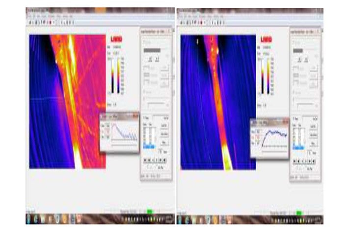
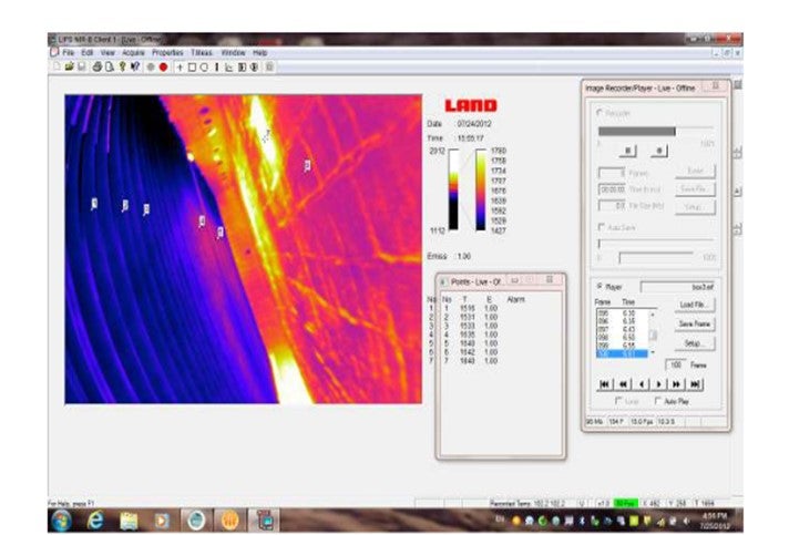
Recently JM has developed with LAND, one of the leaders in SMR TWT pyrometry, the Reformer Imager which provides much more efficient and complete monitoring of the SMR. The Reformer Imager overcomes many of the limitations that exist with pyrometry techniques. Fitted on a probe of 2.2” diameter as shown below, the borescope lens captures HD videos, which typically ranges from 15 to 30 fps operating effectively in a temperature range of 1100°F to 3300°F. Each frame captures ~324,000 temperature data points in high-definition mode. The wide-angle field of view allows users to be able to identify areas that are challenging to locate by the human eye during visual inspection, as it provides sight of almost the entire lane from the peep door. The HD capabilities of the borescope provide focus along the width of the furnace. Operating near infra-red, i.e., at 1μm, the Reformer Imager is able to accurately measure temperature, with a stated tested accuracy of 1% of the measurement. The probe can be inserted into the furnace for multiple seconds of exposure to ensure completeness of readings from a peep door.

The aability to look at an image from all angles allows users to collectively pinpoint and dissect certain areas within the frozen frame image providing full SMR TWT inspections in about a third of the time. Because of the completeness of the data acquisition and accuracy, challenges of existing pyrometry techniques such as visibility, location, vibration, field of depth (visibility), operator variance are removed. The images below show how the data can be highlighted to look at TWT’s along a level of the row of tubes, profile along the length of a particular tube, or spot temperatures within the frozen frame image making a step change in the ability to effectively monitor SMR tubes.
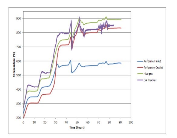
Separate from TWT measurement and monitoring from the furnace side of the reformer, JM has developed, with Daily Thermetrics Corporation, the SMRCatTracker®. (CatTracker® is a registered trademark of Daily Instruments the parent company of Daily Thermetrics Corporation.) The SMR CatTracker® allows an operator to measure on-line process side temperatures within the reformer tube. The SMR CatTracker® is a 1/4” probe with 11 sensing points that is inserted into select reformer tubesalong with the reforming catalyst. Every sensor is designed and manufactured to +/- 0.8°C @ 427°C to provide excellent accuracy at SMR process temperatures. The SMR CatTracker® is connected into the plants DCS system to provide online process gas measurement down the SMR tube.

As described above, SMR TWT measurements are used to indicate mal performance of the steam methane reforming reaction within the SMR tubes and SMR tubes are most vulnerable during transients when much of the instrumentation is challenged to provide accurate measurements. As shown in the graphic below, the SMR CatTracker® accuracy provides very responsive measurement of process gas temperatures even during transients. This allows operators to respond quickly to undesirable changes in operation that lead to mal performance and potential overheating of SMR tubes. The SMR CatTracker® is one of the best ways to provide SMR operators the ability to see online and quickly respond to what is occurring inside the SMR tubes.
Gopi Sivasubramanian (Foster Wheeler USA Corporation)
Normally the reformer firing control is based on outlet manifold temperature and or bridge wall temperature.
Foster Wheeler’s Terrace Wall reformers have an inherent design advantage of providing stable temperature profiles for the catalyst tubes that prevents overheating of the catalyst tubes.
Pat Bernhagen (Foster Wheeler USA Corporation- Fired Heater Division)
Proper control of TMT (tube metal temperatures) comes from proper process flow distribution and proper burner flame shapes. It is desirable to operate near the normal design process flow rates to maintain the internal heat transfer coefficient and back pressure related flow distribution to the various cat tubes. This means at turndown especially high turndowns that the S/C ratio be increased to maintain enough back pressure to distribute the flow evenly into the cat tubes. The increased steam will increase the coefficient and lower the TMT. On the burner side, flame shape and stability is critical to keep the flames from impinging on the tubes. Burners should be operated at fuel pressures and compositions that the burner was shop tested and verified. The tips must be maintained and clear of debris/deposits. The design draft at the burner must be maintained. All burners should be on and with proper air register settings. Reformer designs that use a stabilizing wall for the flames are inherently better maintaining the flame shape and stability. Burners not fired against a bluff body, especially firing downward, have a greater need of monitoring of draft, air, fuel and register settings. Thermocouples in the outlet manifold at various points allow monitoring of outlet temperature variations indicating different heat transfer in certain tubes. Banding of the tubes – hot then cooler section along the cat tube usually near the top- indicate a poor AFPM 2014 Q&A Answer Book 35 catalyst load or catalyst poisoning in the hot region. There are new in tube catalyst thermocouple devices on the market to have an online monitoring of the process temperatures. Also, there are some TSTC (tube skin thermocouple) devices that claim to stand up to the high temperatures that these cat tubes run. In any fixed monitoring case (TSTC or in-tube TC) a pyrometer scan on a regular basis is recommended. This scan sees all the tube length and should cover any area where a TC is to verify its reading.
Pat Bernhagen (Foster Wheeler USA Corporation- Fired Heater Division)
Foster Wheeler Fired Heater Division- Most owners take the unit down and pinch off the top and the bottom pigtail with a double crimping device and physically separate the pigtail from the cat tube. Itis recommended that the cat tube also be removed. This prevents a damaged or unused tube from distorting and affecting adjacent tubes or perhaps even falling in the firebox causing other damage. If the tube stays or is removed the support system must be evaluated especially if multiple tubes are on a single support system. It has been noted that some specialized companies can crimp the tubes on-line with certain designs; the Terrace Wall Reformer is one of these. The feed is pulled out, steam still flowing, firing reduced and effectively not making H2 during this time period but shutdown and start up (a thermal cycle on the cat tubes) are prevented.
Ken Chlapik (Johnson Matthey Process Technologies)
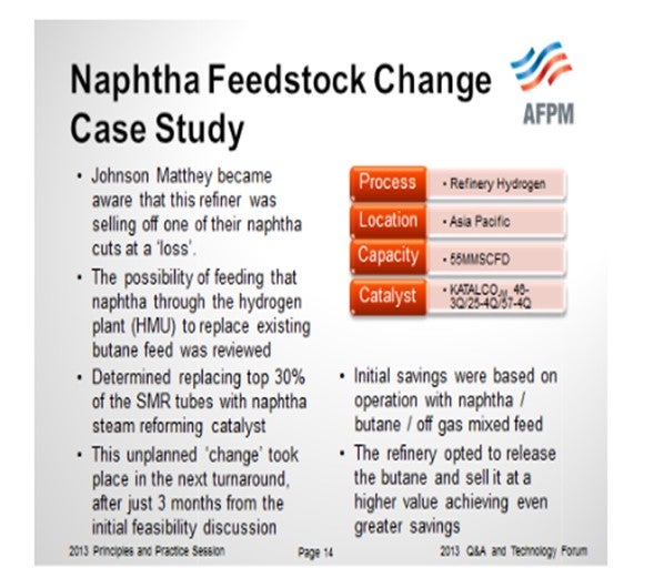
Johnson Matthey has vast experience in direct reforming of naphtha feedstocks in SMR’s for hydrogen production. The naphtha needs to be vaporized to be processed in the SMR based hydrogen plant. It takes less heat load to reform a mole of naphtha as compared to natural gas, but more COx will be produced, and the carbon formation potential is higher in naphtha which can have an average carbon content of C6 and a tail to C20. Because of this, each case needs to be evaluated for changes in feedstock purification, operating conditions such as S/C, reformer catalyst loading, the water gas shift section’s ability to process the higher CO conversion demand, and PSA recovery or CO2 purification issues to hydrogen purity.
At last year’s 2013 AFPM Q&A’s Hydroprocessing Principles and Practices session on “Benefiting from Emerging Hydrogen Sources” a case study was presented on changing to a naphtha feedstock as shown below. The case study highlighted a low or no value naphtha cut being available in the refinery. Johnson Matthey evaluated replacing the existing butane feed which had a much higher market value than the naphtha. The plant was able to put the changes in place after 3 months and pay back the costs of this change in months. As availability of naphtha grows from increased natural gas production and particularly in refiners that are more centrally located in North America, direct naphtha reforming in SMR based hydrogen plants presents an option to process this naphtha.
.
Gopi Sivasubramanian (Foster Wheeler USA Corporation)
Foster Wheeler USA has designed plants with liquid naphtha feed stocks. The naphtha feed is vaporized. Besides the design issues that are to be accounted for the feed section, there are other areas of the plant that would require some modifications to handle.
Use of naphtha as fuel requires project/ site specific analysis with respect to safety/ firebox operations, design of fuel conditioning skid and burner system.
Pat Bernhagen (Foster Wheeler USA Corporation)
The Terrace Wall Reformer has been used for years in services with liquid or naphtha feeds using the split load of catalyst. The low flux of the inlet region of the cat tube and the countercurrent process to flue gas flow provide the ability to handle these feeds.
Deepak Agarwal (Criterion Catalysts & Technologies)
One can use thermometry to provide insight on performance and when to optimize. Utilizing a process model to compare actual temperatures vs. estimated slip will give you an idea of adjustments required. Too high of N slip will require additional HC temperatures to reach target conversion, thus operating to a target/design N slip will help optimize the HC catalyst. We try to calculate N-slip based on heat release across the treating and cracking beds. We run our kinetic model to predict N-slip from the treating reactor on the basis of total observed treating bed delta T. On the basis of actual unit operating WABT and calculated N-slip we try to re-balance the reactor temperature profile to maximize unit cycle life and improve product selectivity.
One can also sample the product for N slip and adjust HT WABT against expected or target value. Reactor inlet temperature adjustments that is greater than the deactivation rate is also another parameter that can be monitored to help optimize catalyst utilization.
Paul Zimmerman (UOP)
Hydrocracking units without an intermediate sample point between the pretreating and hydrocracking catalysts are becoming more common due to units with both catalyst types in a single reactor or due to reluctance or safety concerns with taking the inter-reactor sample. Without the sample, it is difficult to optimize between the pretreating and hydrocracking catalysts. Knowing the nitrogen slip from the pretreating catalyst allows determining the relative performance and stability between the two catalysts to make optimum use of each. Over-converting of nitrogen can result in accelerated deactivation the pretreating catalyst. Under-converting of nitrogen can result in higher temperatures for the hydrocracking catalyst along with reduced yield selectivity and product quality.
Without the intermediate sample, judgment must be made based on the information available, although this is difficult to do accurately. First priority is that both catalysts must be operated within the safe operating limits of the unit including heater duty, quench availability, and bed temperature rise limits. If these conditions are satisfied, then the bed temperature rise, and feed properties can be considered.
The total temperature rise of the pretreating catalyst is the primary indication of hydrotreating severity. To interpret that total rise, the sulfur, nitrogen, aromatics, and olefins in the feed all must be considered as these all contribute to the temperature rise. Often, the nitrogen may be the lowest contributor to the pretreating temperature rise, which greatly complicates estimation of the nitrogen slip.
With a given feed composition, the relative temperature rise between pretreating and hydrocracking can be considered. A decreasing pretreat temperature rise along with increasing hydrocracking temperature rise may imply a shift of the hydrotreating reactions to the hydrocracking catalyst. In this case, a higher pretreating temperature may return balance to the catalyst severities.
In the past, a decreased temperature rise in the first hydrocracking bed was interpreted as an increased nitrogen slip, particularly with noble metal catalysts. However, today’s base metal hydrocracking catalysts are more nitrogen tolerant and can often have a significant temperature rise from hydrotreating reactions alone. Therefore, the hydrocracking temperature rise may not always be reliable for this purpose.
Deepak Agarwal (Criterion Catalysts & Technologies)
PCA (Poly Cyclic Aromatics) formation is not a function of processing synthetic or opportunity crudes. Some opportunity crudes can be much easier to process by a HCU due to much lighter EPs thus providing extended run lengths. Feed type, quality, severity of the operation, unit configuration and catalyst choice in the HCU are determining factors for PCA formation.
Units which are designed for very high conversion and recycling back to feed are always candidates for dealing with PCA formation. Unfortunately, most refiners have to increase bleed rates to mitigate PCA issues since there are no easy catalytic solutions and buildup of PCAs is mostly a function of recycle rates. Since PCA formation is also a function of temperature, operating the catalyst systems as cool as possible will directionally minimize PCAs production. Selection of most active catalysts available will allow operation at lower temperatures.
Paul Zimmerman (UOP)
Processing of synthetic or opportunity crudes can often present challenges to hydrocrackers due to increased refractory sulfur and nitrogen, multi-ring aromatics, and asphaltenes. The multi-ring aromatics and asphaltenes directly contribute to HPNA formation at the acid sites of hydrocracking catalysts. In addition, refractory nitrogen leads to higher operating temperatures further promoting HPNA condensation reactions. If allowed to increase, operating with high HPNA will cause increased catalyst deactivation, fouling of effluent exchangers and air coolers, and decreased yields and product quality.
The traditional method for controlling HPNA is to reduce conversion. This in effect is removing HPNA by a bleed stream at the rate created in the reactor, of which HPNA will have an equilibrium level. Reducing feed endpoint has also been effective for managing HPNA. In general, feeds with greater amounts of HPNA precursors will require greater endpoint reduction. Endpoints are often limited to 750-850 °F for FCC cycle oils, 900-1000 °F for coker gas oils, and 1000-1100 °F for straight run oils. Forsynthetic crudes, this may require understanding of upstream processing at the upgrader to determine the HPNA potential. Additional operating factors to limit HPNA may include higher hydrogen partial pressure, higher H2/oil ratio, and maximum saturation catalyst.
UOP also has engineered solutions to manage HPNA and allow higher conversion. These include technology solutions that remove HPNA via fractionation or selective adsorption. These HPNA solutions can often allow increasing conversion close to 100%. This may provide a significant advantage if the refiner doesn’t have the ability to upgrade the unconverted oil to a higher value product, such as in an FCC.