Question 54: Please discuss the pros and cons of the various forms of desalter level indicator technologies
Year
2011
Process
Tom Collins (Forum Energy Technologies)
On some occasions more frequent, or continuous mudwash may help dilute effluent water, thus reducing high concentrations of solids slugging the effluent water exchangers during the mudwash cycle.
George Duggan (Baker Hughes)
We have extensive experience removing calcium and other metals from crude oils, with over 20 successful applications removing contaminants spanning the last 8 years. These experiences allow us to tailor programs for customers not only in terms of contaminant removal, but also with regard to downstream corrosion, environmental and product quality concerns. As already mentioned, carboxylic acids are often used for contaminant removal, although mineral acids such as sulfuric acid have also been applied. Since many of the acids will provide some degree of negative side effects, the choice of acid becomes most critical. For example, acetic acid has been shown to have severe impacts on emulsion band growth and waste water plant upsets. Acetic acid also has a severe, negative impact on overhead corrosion, due to its greater tendency to partition to the crude oil in the desalter. Citric and oxalic acids are particularly bad options due to low solubility of calcium salts, which causes major desalter fouling issues. Our patented EXCALIBUR contaminant removal technology utilizes acids that are selected to provide the optimum calcium removal while avoiding negative consequences. With EXCALIBUR, we have documented successful calcium removal while, at the same time, providing improved COD in wastewater plants, no concerns with desalter equipment fouling and minimal impacts on overhead corrosion. Preheat fouling can be a concern regardless of acid choice, due to evaporation of water in the desalted crude, which leaves salt deposits behind. Experience shows, however, that preheat fouling is rarely a major concern. In those few cases where fouling occurs, the salts can be easily removed with periodic off-line water washing. If offline washing is not an option, proven, low cost antifoulant treatments can be utilized to minimize fouling impacts.
(EXCALIBUR is a trademark of Baker Hughes Incorporated)
Gary Gianzon (Marathon Petroleum Company)
Marathon Petroleum Company LP (MPC) main concern when processing high calcium resid was calcium fouling the lower convection section and upper radiant section of the coker furnace which will make it difficult to online spall. As a precaution, we initially set calcium target at a very low concentration and have been monitoring and steadily raising the calcium limit as we gain experience in processing these types of crudes. The heater has been successful in online spall several times so our initial fouling concerns were not warranted.
George Duggan (Baker Hughes)
Along the lines of Ron’s last point on secondary treatment of brine, some refineries have installed diversion tanks to receive the effluent water when the mud wash is being used. Other refineries have installed various designs of break tanks in the run down from the desalter effluent to try to break out as much oil and solids before the water reaches the WWTP (waste water treatment plant). Much depends on how the refinery waste water system is configured. We have had success chemically treating the desalter brine as a dedicated stream, breaking emulsions, while allowing for the removal of both the insoluble particulate and dispersed oil prior to entering the WWTP. One important point is to isolate the solids such that they are not returned to the crude unit via slops.
Tom Collins (Forum Energy Technologies)
(a) Laboratory testing should be performed on the crude to measure filterable solid size distribution and type. Filters should range from 0.45 micron down to 0.1 micron, and should be used on both the raw crude and the interface emulsion. Once data has been generated, then a operating program can be considered to best deal with your particular situation.
(b) Some refiners have used secondary treatment equipment ranging from centrifuge type applications, to simple break tanks where additional chemicals may be employed for further separation. Typically the oil recovered from equipment using water clarification type chemistry is not a good candidate to be reprocessed in the desalter.
George Duggan (Baker Hughes)
While general limits are assigned for overhead chloride levels, the reality is that these are simple rules of thumb and should not be relied on to provide satisfactory corrosion control for most systems. Our experience has shown that overheads can experience serious corrosion problems with chlorides as low as 5 ppm and we’ve seen systems with no corrosion problems when chlorides are 50 ppm. Each overhead system should be examined independently to determine an allowable chloride limit. Rigorous simulation modeling is required for each overhead system to determine the chloride level which will avoid both salt formation and acidic aqueous corrosion. We use the Ionic Model developed by Shell R&D and licensed only to Baker Hughes to carry out the modeling analyses.
Once a chloride target is established, caustic use, with appropriate injection and usage limits, is a proven means to achieve and maintain that chloride target.
Rajkumar Ghosh (Indian Oil Corporation)
Typically, vacuum unit ejector systems have three ejector stages in series. Large crude vacuum units have multiple three-stage ejector system in parallel. Our system is designed with three-stage ejectors, each having three parallel ejectors with capacity distribution of 1/7th, 2/7th and 4/7th. We keep 4 to 5 ejectors (out of total 9) in line based on the requirement for maintaining the target vacuum level of 25 mm Hg(a). The average steam consumption is 60% of the design consumption.
The ejector systems have typical arrangement of ejector-condenser pairing, which reduces the load on the downstream ejector. The ejectors are sized based on predefined gas load, which consist of non-condensable (air + cracked gas), steam and condensable oil vapors. To ensure air leakage into the vacuum column is within acceptable limit, vacuum holding test (fall in vacuum <5 mmHg/hr) is carried out during commissioning and after every M&I shutdown. Generally, design incorporates enough margin to accommodate higher than normal air leakages that may be resultant of emergency shutdowns and start-ups.
Ejectors performance is expected to follow ejector performance curve, provided by the manufacturer as long as the motive steam pressure and temperature are kept close to design. However, comparing actual performance with performance curve is not easy as the estimation of gas flow often poses difficulties. In practice, we monitor the vacuum level and steam consumption for any unusual deterioration. It may be a good idea to provide a non-contacting type flow meter for estimating the non-condensable gas going out to furnace from the last stage ejector.
The under-performance of ejectors will be reflected in higher Vacuum column pressure. When an ejector system is under-performing, it is necessary to determine the specific cause for the underperformance. The process of troubleshooting is often by the process of exclusion. In our units, we have observed deterioration in the performance of ejector system due to following reasons:
a. Fouling in the inter-condensers is the most common cause for fall in ejector performance. We had couple of occasions, where the Fills from the cooling tower packing clogged the channel of the 1st ejector condenser. We had to take unplanned shutdown for the quick clean-up. Finally, we had provided a simple back-flushing system on the cooling water side, which paid rich dividend.
b. We also had occasions where, there was gradual deterioration of the ejector performance due to erosion in the ejector nozzles and had to replace the nozzles during the unit turnaround. Steam supplied to the system should be clean and dry. The header should be equipped with strainer and steam trap arrangement, and they should be maintained in proper health.
c. There are also occasions, when the vacuum column pressure gets temporarily elevated, which are generally traced back to inadequate long residue stripping in the atmospheric column.
Temperature and pressure values for the complete ejector system (upstream and downstream of each stage) are essential pre-requisite for effective troubleshooting of most ejector system. The field values are compared with the design data to ascertain the problem areas.
We have not done any modifications in our vacuum ejector system. Steam consumption is optimized by taking some of the parallel ejectors on-line or off-line based on the vacuum level in the column. We try to ensure that our spill-back valve remain closed all time.
Gary Gianzon (Marathon Petroleum Company)
Within the Marathon Petroleum Company LP (MPC) refineries we have multiple examples of first stage ejector configurations, ranging from a single ejector to three in parallel. In the systems that employ multiple first stage ejectors all are kept in operation. In the systems with multiple ejectors, the design load from the vacuum column has been split evenly across the ejectors.
An evaluation of the ejector system starts with the ejector performance curve provided by the ejector manufacturer. This is an example of a performance curve for a first stage ejector, and is typical. The minimum motive steam pressure, with temperature, is listed along with the maximum discharge pressure of the ejector. These two variables must be satisfied before any determination of adequate sizing and optimization can be made. If either the motive pressure is below the design point or the discharge pressure is above the maximum design point, the ejector would be expected to break and not perform as designed. When these two design variables are met, a properly functioning ejector will follow its performance curve.
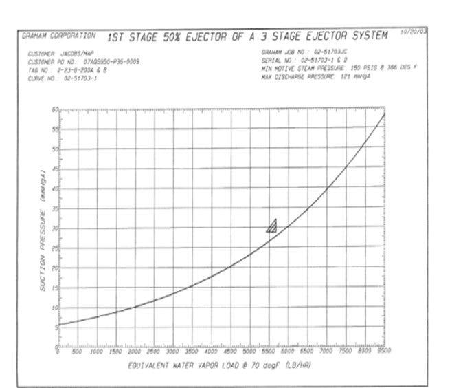
The performance curve is a plot of the equivalent water vapor load from the tower against the suction pressure of the ejector. In this example, the ejector was designed to process 5,757 #/Hr of equivalent water vapor from the tower at a suction pressure of 28.8 mmHgA. At a tower load less than this amounts the suction pressure will drop accordingly, following the curve. In converse, if the ejector load is higher than design the resulting suction pressure of the ejector will be greater. If the ejector is following the curve, it is considered operating per design and no further optimization is warranted. An ejector operating at a point above the curve would be an indication of a problem with the ejector system with further troubleshooting required.
In systems that employ multiple ejectors the load from the tower can be evaluated and an ejector shut down to reduce steam consumption. This is the only avenue for reducing steam consumption, as the minimum motive steam pressure is set by design. The tower load would subsequently be distributed across fewer ejectors, with the performance curve followed to determine if the resultant inlet pressure is acceptable. This is certainly a feasible option during turned down operation. Depending on the configuration of the first stage condensers, the tower load may be then processed across fewer condensers also, with a possible unacceptable increase in pressure drop. The ejector outlet pressure must be confirmed to be below the maximum allowable pressure for the remaining ejectors to function properly.
MPC has not made modifications to reduce steam consumption, except in turned down operation. Rather, MPC strives to take advantage of the reduced tower pressure.