Question 96: What are your experiences using SOx reduction additives formulated with lower rare earth content?
Ray Fletcher (Intercat)
Cerium oxide functions as an oxidant and oxygen carrier: the mixture of two oxidation states Ce(III) and Ce(IV) creates defect sites in the crystal structure where oxygen ions are missing (oxygen vacancies) – these get filled up in the regen and ceria acts as a kind of monatomic oxygen sponge. Monatomic oxygen is more reactive than O2 hence ceria catalyses oxidation reactions. Also mixing in the regen is effectively improved as oxygen is transported around the regen as the particles move around.
Most other oxidants don’t do this (e.g., Pt promotes oxidation when two molecules meet on its surface, it doesn’t sponge the oxygen). So, ceria does play a rather special role. Simply decreasing the amount of ceria works to some extent, but clearly a point will be reached where efficiency drops off.
Intercat has developed and commercialized SOx reduction additives containing 50% less cerium. What Intercat has done is to “extend” the functionality of ceria by proprietary methods to improve the overall oxidation activity of the additive thereby allowing the ceria content to be decreased at equivalent performance. At present, there are now over 28 users of this technology. In every application the lower concentration cerium additive has performed equal or slightly better than the standard SUPER SOXGETTER.
Further, Intercat is utilizing proprietary technology developed within its new owner, Johnson Matthey, for further enhancements in cerium dispersion together with new oxidation packages which will enable a 75% or greater cerium oxide reduction. These technologies include the careful construction of the physical structure of the microsphere, deployment of manufacturing technology which controls both the location and the local concentration of the cerium particles plus the addition of co-promoters to the additive. These techniques have made it possible to improve the overall oxidation activity of the additive thereby allowing the ceria content to be decreased while maintaining equivalent SOx removal performance. Two trials of this technology have been initiated and are being base loaded into two North American refineries now.
Intercat, as well as other additive suppliers, has developed rare earth free SOx reducing additive. These additives of course are lower in cost but generally require much higher concentrations in the circulating inventory. Depending on the composition of the additive this may lead to cracking dilution and possibly loss in product yield. However, it is recommended that refiners employing SOx reducing additive consider these technologies in addition to the high activity additives described moments ago.
Matthew Meyers (Western Refining)
Western Refining LLC has recently trialed several SOx reduction additives with lower levels of rare earth. The first was at half the typical rare earth levels. At 1% dosing, the result was a pickup factor of roughly 15. The second addition had zero rare earth and provided a pickup factor of roughly 5 at close to 3% dosing.
Eric Griesinger (Grace Davison Refining Technologies)
Grace Davison’s SOx reduction additives, formulated with lower rare earth content to lessen the impact of hyperinflationary costs associated with rare earth compounds, have gained wide acceptance. Within Grace’s portfolio of SOx additive products and its accounts, customers that were able to make a change to lower rare earth formulated SOx additives have done so. FCCU locations currently operating under EPA Consent Decree trial protocol have remained with the original formulation available at the start of their trial periods. Only two additional refineries are in the midst of evaluations between Grace’s Super DESOX® additive and Grace’s alternative products. Otherwise, all of Grace’s globally situated customers, existing and newly acquired, are utilizing SOx additives formulated with lower rare earth content. Grace offers three new SOx reduction additives: Super DESOX® OCI, Super DESOX® MCD, and Super DESOX® CeRO. Super DESOX® OCI, optimum cerium input; mitigates costs associated with rare earth compounds, while demonstrating on par pick-up-factor efficiency to Super DESOX® additive. Super DESOX® MCD, maximum cerium dispersion, further reduces rare earth cost exposure, yielding suitable and cost-effective balance between SOx transfer ability and slightly increased dosing rate. Additionally, Super DESOX® CeRO is formulated without rare earth compounds. All three of these new products build on the success of Grace’s Super DESOX® additive performance. These offerings provide refiners with a range flexible option, enabling a balance between rare earth inflationary exposures and dosing rates, to achieve SOx emission compliance.
Below is an example of a refiner that historically utilized Super DESOX® and then switched to Super DESOX® OCI. Observed is the ability of Super DESOX® OCI to continue controlling SOx emissions within limits, at comparable dosing rates as was the case with Super DESOX®. Utilizing Super DESOX® OCI over Super DESOX® can result in a SOx additive cost reduction roughly 35%.
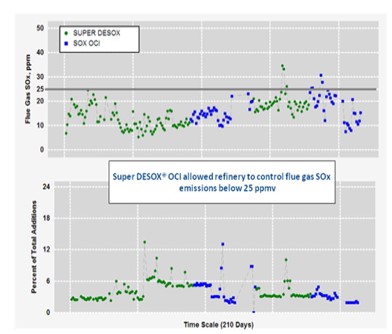
Additionally, Grace Davison’s laboratory scale research indicates that the partial burn environment performance of Super DESOX® OCI and Super DESOX® MCD is similar to that of Super DESOX®. Please contact your local Grace Davison sales and technical service representative for additional insight specific to your application.
Year
2011
Process
Question 34: What are your current protocols, practices, and concerns for using wireless communication between field instruments and the control room? Would wireless communication be acceptable for monitoring only, or is control allowed as well?
LOGEROT (Prosys Inc.)
The question asked about the protocols. But rather than naming the protocols, I think it would just be best to describe what the installation looks like. With wireless transmitters that are in use, you are usually installing a mesh network and you have a Modbus gateway connected to the DCS. You have a separate wireless gateway that is connected to that as well, and the wireless gateway connects to all the transmitters. Each one of the transmitters can actually act as a hub and is able to receive and transmit data with the other transmitters. That way, transmitters can find other transmitters close by and multiple pass-backs to the gateways. So, if a transmitter is out of service for any reason, the other transmitters will basically find pathways around it to get communication back to the wireless hubs.
Note that in this kind of arrangement, you need to have a robust gateway; because basically, the wireless gateway represents a single point of failure. Therefore, most installations use redundancy there, sometimes triple redundancy, to make sure that communication stays open.
Where are the main uses of wireless in refineries today? In our experience, they are usually remote areas of the refinery where a signal and power wiring are not easily run out. The big advantages, obviously, are cost savings, conduit wiring, and cable trays. Inside the battery limits of, say, a crude unit, wireless is not as common. Where used, it is usually for auxiliary type of measurements such as corrosion monitors, vibration monitors, additional temperatures, and pressures that are not central to the process. You might also consider wireless technology, as sometimes we have outside operators who have handheld devices that are wirelessly connected back to the control room. For that one-ring device, there will also be a network of gateways available for the wireless device to communicate back to the control room.
What are the concerns associated with wireless technology? The first real concern is cybersecurity. I mean, everyone is concerned about security these days. Basically, every wireless device and transmitter in your plant represents a potential entry point for intruders. So, you have to be very careful to put in strong security protocols to make sure that intruders will not get into your network. What can happen from an attacker? An attacker can jam your signals. You could lose proprietary data, and – worst of all – an attacker could end up gaining control over part of your process. You really do not want that to happen, which is why security is a big concern when using wireless. Second is overall reliability. Basically, we have been using hardwired signals for decades. Wireless signals are just not as robust in today’s technology as are the hardwired signals. For example, how often do you have to go reset the Wi-Fi in your house? That is an example of when wireless is not as reliable as it could be.
The last part of the question had to do with whether wireless is acceptable for control or if it is just for monitoring purposes. When I say ‘control’, I am talking about closed-loop control where you have a wireless transmitter communicating to the control room and there is a control action. They then signal out to the final element, usually a valve. It is probably also wireless, but it might be hardwired; but there is at least some component in that closed-loop control that is wireless. Our typical answer is that it is just not used very often for closed-loop control, and it is usually not recommended. One of the problems is battery life, because the transmitters you are using in the field are battery-operated. If you have a very high refresh rate – like, typically, a five-second refresh rate, then your batteries will die too quickly. That is one reason why you would not want to be using wireless for controls. So, generally speaking, it is not recommended or used. However, that is not to say that wireless control will not, sometime in the future, be relatively common.
THEISS (Marathon Petroleum Corporation)
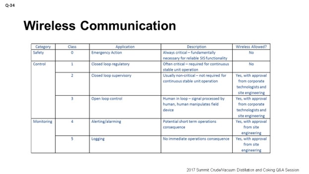
The chart on the slide is really the internal guidance we use at Marathon. You can see that for what we call Class 0 and Class 1, we do not allow wireless communication, which basically inputs to an SIS (safety instrumented system) or some control point that is detrimental to the process. An example of a detrimental control point would be an FCC (fluid catalytic cracking) reactor/regenerator pressure differential transmitter for which we would not allow wireless control.
There are a couple of applications in which we allow control. I do not think they are widely used within Marathon; but with some corporate guidance and corporate technologist approval, we can use them wireless for control. These would be considered Class 2. An example would be a tray tower control for a temperature.
As you move further down the chart to Class 3, you can see an example of where you have the overhead water boot. You have a remote signal that goes into the board, but it relies on the operator to go out and make the move to drain that water boot and start to pump or open up a valve. Class 4 and Class 5 are really for informational purposes. My example for a Class 4 would be a secondary alarm on a tank where you have a primary alarm that is hardwired in and a secondary level or a backup level that could be used remotely. Class 5 would be temperature indication on heat exchangers just to gather data for fouling.
JEREMY THEISS (Marathon Petroleum Corporation)
Technology continues to progress in this field. Since 2011, we have had guidance that allows some usage of wireless instrumentation, but this technology is limited based on application. The table below identifies our stance on certain applications.
|
CATEGORY |
CLASS |
APPLICATION |
DESCRIPTION |
WIRELESS ALLOWED? |
|
Safety |
0 |
Emergency Action |
Always Critical: fundamentally necessary for reliable SIS functionality |
No |
|
Control |
1 |
Closed-loop regulatory |
Often Critical: required for continuous stable unit operation |
No |
|
2 |
Closed-loop supervisory |
Usually Non-Critical: not required for continuous stable unit operation |
Yes, with approval from corporate technologists and site engineering |
|
|
3 |
Open-loop control |
Human in Loop: Signal processed by human, human manipulates field device |
Yes, with approval from corporate technologists and site engineering |
|
|
Monitoring |
4 |
Alerting/alarming |
Potential short-term operations consequence |
Yes, with approval from site engineering |
|
5 |
Logging |
No immediate operations consequence |
Yes, with approval from site engineering |
Examples:
Class 0: Inputs to a Safety Instrumented System
Class 1: FCC Reactor/Regenerator pressure differential transmitter (used to manipulate flue gas stack valve)
Class 2: Tower tray temperature
Class 3: Water boot high/low level where control or field operator starts/stops a pump or opens/closes valve
Class 4: Storage tank secondary level alarm
In most of the approved applications, redundant wireless gateways are required to minimize disruptions to a failed gateway. Other points to consider for determining if wireless is acceptable include the required scan rate of the application, wireless distance limitations, and potential for wireless interference. Guidelines should be made to ensure battery life or alternate power to the wireless device is sustained and has monitoring capabilities.
DARWIN LOGEROT (ProSys Inc.)
Wireless Protocols
Rather than naming the protocols in use, it is probably better to describe the installation. Where wireless transmitters are in use, they are often installed in a mesh network similar to cellular towers or a Wi-Fi network with multiple hubs. A Modbus gateway is connected to the DCS and to the wireless gateway that is connected to all the transmitters. Each wireless transmitter acts as an individual hub and is able to receive and transmit data with others. This way, a transmitter can find other transmitters close by and have multiple paths to the wireless gateway. If one or two transmitters are out of service, the remainder will adjust to provide continuous communication.
In this arrangement, a robust wireless gateway is important. If only one wireless gateway is provided, it can represent a single point of failure, potentially losing view of all instruments using that path to the DCS. Users will typically install redundant gateways to mitigate this.
So, where are the main uses of wireless technologies in refineries today? The locations are usually remote where the signal and power wiring are not readily available. The big advantage is cost (savings in conduit, wiring, cable trays, power distribution, etc.) and the ability to monitor remote data, such as in a large, spread-out tank farm.
Inside a refinery process battery limit, use of wireless is not so common. Where it is used, some of the more common wireless applications are in corrosion monitors, vibration monitors, and additional temperature and pressure monitoring on vessels and exchangers (auxiliary to the hardwired temperatures and pressures).
Another use of wireless technology is for hand-held devices used by field operators. With this arrangement, another mesh network is employed to connect the wandering device to the DCS. The field operator can use the device to monitor operating conditions, execute periodic rounds, and take notes regarding observations. Major DCS manufacturers are offering this technology as an extension of the control system, but the control itself is done with hardwiring; only monitoring and setpoint adjustment are done through wireless.
What are the concerns associated with wireless technology?
First and foremost is cyber security. Every wireless device represents a potential entry point for an intruder. Security protocols are better and stronger now than ever, but many potential users are still reluctant to install extensive wireless devices. Security concerns include the possibility of wireless signals being jammed by an attacker, potential loss of proprietary data, or, worst of all, an outside intruder gaining control of part of a process.
The second concern is reliability. Wireless communication generally is less robust than hard-wired connections.
A third concern is the data refresh rate and its connection to battery life. For example, a one-minute update rate on the transmitters was tied to a life of about 10 years, whereas an update rate of four seconds reduced that life to two years. The relationship between refresh rate and battery life, of course, impacts how wireless can be used for basic control and impacts wireless maintenance costs.
So, is wireless communication acceptable for process control?
Allowing for a slightly wider definition of “wireless control”, it is in widespread use today – the plant radio. For example, the console operator can contact the outside operator: “Hey, go open/close the bypass valve around the control valve that is not working.” But more seriously, purely wireless communication for process control in a refinery is seldom used or recommended, especially in a unit that is tightly connected geographically, such as a crude unit or FCC. Where wireless communication is in use, it is almost exclusively for monitoring only, primarily due the problems outlined above. The closest approach to wireless control is using the handheld devices to adjust setpoints. The control itself is still through hardwire communications from the transmitters to DCS controllers and to the valves.
That said, there is no reason to expect that as technology improves, the current problems will not be overcome, at least in part. Perhaps future refineries will include widespread use of wireless process control.
Year
2017
Process


Question 40: As it relates to overall catalyst cycle life management, please address the following issues: What are typical cascading practices for catalyst reuse after regeneration and eventual disposal that you employ? What quality control, catalyst properties and performance specifications, and/or warranties do you have in place for regenerated catalysts? What are some of the key decision criteria you use in determining whether to send a catalyst for metals reclamation, r
JAMES “TIM” CAMPBELL(Eurecat U.S., Inc.)
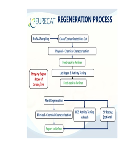
First, a response to the question: What are typical cascading practices that you employ for catalyst reuse after regeneration and eventual disposal? As the leading catalyst regenerator, Eurecat sees NiMo and CoMo hydrotreated catalysts (regenerated and regenerated plus rejuvenation) in ULSD, jet, kerosene, naphtha, and gas oil hydrotreating units. There is growing use of regenerated hydrocracking catalyst. These regenerated catalysts, or those regenerated and rejuvenated, may be used as an entire load or a partial load, depending on the specific application. Catalyst reuse management can provide substantial savings to the refining organization.
The second question concerned quality control, catalyst properties and performance specifications for regenerated catalysts. Eurecat has specific catalyst regeneration specifications for:
*Contamination metals (such as Si, As, Fe, Ni, V, Ca, Na),Physical (length/diameter, length distribution, and crush strength),
*Pressure Drop (measurement regenerated catalyst pressure drop versus fresh catalyst), and
*Activity (measurement of HDS activity versus fresh catalyst).
LIFENG ZHENG (Criterion Catalysts & Technologies)
Depending on the condition of the catalyst post regeneration, the catalyst can be cascaded to a less severe service [USLD to kero (kerosene), kero to naphtha, etc.] where the catalyst performance is less sensitive to activity. Regen can also be used on non-activity-constrained higher performance units or in units slated for a short cycle due to turnaround planning in, for example, the top bed of ULSD unit. In certain instances, it may be necessary to install some fresh catalyst to make up for a potential loss of activity and volume of the regenerated catalyst.
After a conventional regeneration and depending on the type of catalyst (Type I or II), the catalyst will typically regain anywhere from 70 to 95% of its fresh catalyst activity. Here your catalyst vendor can give guidance on the expected recovery for the particular catalyst. There will be physical catalyst loss due to breakage and attrition of pellets during unloading and regeneration that will need to be taken into account. Part of a catalyst bed that is unloaded may not be suitable for regen depending on the feed poisons and physical condition of the spent catalyst. Contact the regen vendor for additional details regarding warranties and catalyst properties on regenerated catalyst.
Some refiners actively manage a pool of their own regenerated catalyst because they can keep track of the condition of the catalyst based on the service and feed contaminants to allow cascading. Where it makes sense, Criterion works with the refiner to incorporate the regenerated catalyst into the planned loading for the next cycle. In a recent example, we successfully helped a customer transition catalyst from the bottom bed of a ULSD unit which was prematurely shut down into the top bed of a medium severity FCCPT unit in order to assist the customer with maximizing catalyst utilization.
The business case for selecting metals reclamation, regeneration, or disposal is ultimately based on economics. Regeneration is chosen when a use for the regen catalyst is identified within the refinery, if it is needed in the shared regen pool, or if there is a known market for this particular catalyst load and a third party is willing to purchase it. Service history is critical as catalysts with suspected high poison levels are not suitable for reuse. The catalyst cannot be vacuum-dumped, caustic-washed, or otherwise mishandled if it is going to be regenerated.
If the catalyst is not going to be regenerated, then it must either be reclaimed or disposed. Pricing and yield of precious metal could impact returns on metal reclamation. Reclamation companies usually charge a service fee for processing spent catalyst and give a credit for a portion of the metal reclaimed. Depending on the metals market, the metals credit can cover the processing fee; but with current depressed metals pricing, the credits usually do not offset the costs.
Disposal of spent catalyst is rarely done due to cost and potential environmental impacts. The transportation and disposal of spentcatalysts are governed by DOT (Department of Transportation) and RCRA (Resource Conservation and Recovery Act) regulations. The hazardous waste must be properly disposed of at an approved treatment, storage, and disposal facility.
HENRIK RASMUSSEN (Haldor Topsoe, Inc.)
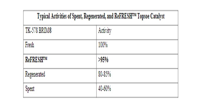
For many years, refiners have cascaded used catalyst from a high severity to a lower severity service within their refinery. In order to do so, the catalyst needs to be regenerated and properly evaluated to make sure the level of poisons on the catalyst is acceptable for reuse in any service. Topsoe has, for many years, offered our proprietary ReFRESH™ technology, which is an add-on to the regeneration procedure. The ReFRESH™ process will restore the catalyst to 95+% of its original fresh activity, thus enabling the refiner to use the ReFRESH™ catalyst in the same service from which it was removed without any noticeable penalty in performance or cycle length.
In order to ensure that the spent catalyst is a good candidate for regeneration, as well as a candidate for the ReFRESH™ technology, we have generated the following guidelines. The spent catalyst should meet the following criteria:
*Surface area greater than 80% of fresh catalyst surface area,
*As(arsenic)lessthan0.1wt%,
*Pb (lead) less than 0.15 wt%,
*Na (sodium) less than 0.3 wt%,
*Si (silicon) less than 1.0 wt%,
*Fe (iron) less than 1.0 wt%,
*No other metal [Ni(nickle), V(vanadium), etc.] higher than 1.0 wt%,
*Total contaminant level less than 2.0wt %,
*Average length of particle higher than 3.0 mm(milliliters) for 1/20” TL (transferline), and
*SCS(syntheticcatalysticscavenger)higherthan2.5lbf/mm (pound-force foot to Newton millimeter).
Catalyst with contaminant levels higher than shown above should be set aside and sent for reclamation, because it is not economically justifiable to spend money on regenerating and investing in ReFRESH™ technology for this material. Every year, Topsoe applies our ReFRESH™ technology to millions of pounds of regenerated catalyst, which are used again in high severity hydro treating applications such as ultra-low sulfur diesel and FCC pretreatment. Many of our clients have used the same catalyst up to three times.
Year
2016
Process
Question 36: What changes have you made to the C5/C6 Isomerization unit to comply with the new benzene regulations; what changes have you made to the refinery operation; and what have been your challenges and successes of implementing the new configuration?
Olivier Le-Coz (Axens)
More severe regulation in term of Benzene in the gasoline pool can lead to increase the Benzene content to the C5/C6 isomerization unit. This can happen in two different ways.
The refinery process operation can be modified to decrease the benzene precursors content in the heavy naphtha to the Reformer. This is achieved by increasing the light naphtha end point in the topping lights ends naphtha splitter, light naphtha being the Isom unit feed. At the same time C7+ in the Isom feed must be limited to 2 – 3 vol% as those products will undergo undesired hydrocracking reactions in the Isom reactors. With such a scheme, straight run naphtha Benzene (native Benzene) is basically treated in the Isom. This approach can typically be applied in the frame of a new project.
When the “pre-fractionation” scheme cannot be implemented or if it cannot allow reaching the overall pool Benzene specification, a “post-fractionation” option can be implemented. It consists in splitting the reformer product and recover a light Benzene rich reformate which will be treated in the Isom unit in blend with the light straight run naphtha. Depending on the Isom unit existing configuration, some modification to the hardware may be required or not. As a matter of fact, Benzene concentration at the Isom reactors inlet should better not exceed certain value to ensure proper operation and performances of the Isom catalyst (about 4 vol%).
-If the Isom unit is equipped with a recirculation, the recirculated stream acting as diluent may allow maintaining Benzene below the desirable value at the reactor inlet. The extra Benzene amount in the feed will be hydrotreated by the Isom catalyst without disturbing too much the operating conditions and without preventing suitable isomerization rate to be achieved.
-If the Benzene content at the inlet of the reactors cannot be maintained low enough (too low or no recirculation), a dedicated Benzene saturation reactor must be added.
In the case of new units implementation, those schemes have proved to work very well. In the case of revamp projects, existing equipment modifications or idle equipment reuse, a through basic design study upfront including the catalytic aspects is strongly recommended.
Brad Palmer (ConocoPhillips)
In general, refineries with C5/C6 Isomerization units or Aromatic Extraction units have increased feed rate and/or benzene content to these units. Reformer octane has gone down due to ethanol blending but, in most cases, Isom octane demand has remained strong. The primary successes include implementing these projects safely and achieving our benzene reduction requirements. Additionally, heavy reformate blend qualities have improved which has made blending premium gasoline easier and has provided additional opportunities for blend component sales.
A number of technology options were chosen by ConocoPhillips refineries to meet benzene regulations according to the existing configuration and site economics. These options include revamping Aromatic Extraction Units (AEUs) to increase feed and benzene production capacity, sending light reformate or heart cut to other AEUs, modifying C5/C6 Isom units to include benzene saturation reactors, new benzene saturation unit construction, reducing benzene production through prefractionation and use of credits.
All completed projects are working, some with very few operating problems and a few with requiring design modifications and/or operating changes. Operating, design and reliability issues continue to be worked to improve unit performance; a few specific examples are provided below.
Isomerization Unit Challenges
-When all benzene saturation reactors are complete, two will have Pt catalyst and four will have nickel catalyst. One of the reactors will have changed from Pt to Ni.
-The units that added a benzene saturation reactor in front of their Isom reactors have had challenges controlling temperatures profiles of all three reactors especially when liquid recycle is added or removed.
-Isom units have heavier feeds (increased X-Factor). One unit has and XF of 30 lv% average (35 lv% highest) and 9 lv% Benzene Average (10 lv% highest). Another unit has an XF of 25 lv% average (27 lv% highest) and 5 lv% Benzene Average (10 lv% highest).
-Determining when and how much liquid recycle is necessary for safe operation while maximizing fresh feed throughput has taken time. Vendors advertise an upper benzene level of 5 lv% to the inlet of a benzene saturation reactor. While we have gone a little higher by lowering the inlet temperature to accommodate the exotherm, this is a good rule of thumb.
-Increased unit rate can impact dryer operation by fluffing up-flow desiccant beds. Higher rates increase HCl loading to existing caustic scrubbers; less than adequate neutralization can lead to corrosion problems.
-Benzene saturation catalyst has been deactivated or poisoned by feed (organic sulfur, H2S, FeS, Chlorides) or hydrogen purity (CO and CO2) problems.
Aromatic Extraction Unit Challenges
- Changes in feed quality have required operations to find new equilibrium; one unit has reported bigger swings in aromatic content with new feed streams.
- Stripper foaming has occurred in one unit.
Ujjal Roy (Indian Oil Corporation)
In India, the benzene specification in gasoline is 1 vol.% max. In order to meet this specification, number of changes in the refinery configurations have been done. (a) Light Naphtha splitter has been introduced to produce C-5 & C-6 isomerization feed. (b) Naphtha splitter modified to reduce Benzene precursor from Reformer feed Naphtha. (c) Reformate splitter has been installed to separate Benzene from the Reformate. Over and above FCC gasoline being a component of Gasoline, for reduction of Benzene, a FCC gasoline splitter has been put to take away the Benzene rich cut called Heart Cut from Gasoline. For meeting benzene regulation in the Gasoline, Isomerisation unit has been designed with catalysts having dual functions – Isomerisation and complete saturation of Benzene. The metal sites are used for saturation of benzene and acid sites are used for isomerisation of C-5/C-6. Up to 9.8 vol.% benzene in feed, catalyst is able to saturate to nil level of benzene in isomerate.
Erik Myers (Valero)
The Valero approach has been to consolidate the benzene rich streams from various refineries and capture benzene as a product stream. This has been accomplished through use of a side draw stream from the reformate splitters and then feeding these streams through a centralized benzene extraction unit.
Year
2011
Process
Question 40: Are there instances where mercaptan treatment of refinery gasoline or naphtha streams is necessary? What are the applicable treatment methods?
Praveen Gunaseelan (Vantage Point Consulting)
As mercaptans are sulfur-bearing compounds, they are one among numerous target species for sulfur removal from naphtha or gasoline streams to meet reactor feed or finished product sulfur specifications. Streams that need to be aggressively treated to low sulfur levels, such as naphtha feed to catalytic reformers, or ultra-low-sulfur gasoline product or blend stock, often require hydrotreating, which targets removal of a broad array of contaminants, including mercaptans.
However, there are a number of instances that warrant targeted removal of mercaptans species from refinery naphtha and gasoline streams (generally achieved through mercaptans extraction or sweetening). Some examples are provided below.
For light gasolines with a high proportion of mercaptans sulfur, selective extraction of mercaptans may be a competitive alternative to hydrotreating. For example, light straight run naphtha or FCC light naphtha with a high proportion of mercaptans sulfur may require only caustic extraction to be rendered acceptable as gasoline blendstock. In the case of FCC light naphtha, caustic treating for mercaptans can help avoid octane loss from olefin saturation during hydrotreating.
Light (C1-C6) mercaptans have an objectionable odor and corrosion potential and are prone to accumulate in refinery naphtha and lighter streams. In instances where naphtha is segregated, such as for use as a feedstock for downstream processing, there may be a need to reduce light mercaptans content to render the material transportable, regardless of the total sulfur content. In such instances, caustic sweetening of the naphtha may be appropriate, where the light mercaptans are oxidized to odorless disulfides.
Besides meeting sulfur specifications, gasoline streams may require meeting a mercaptans specification, such as a negative Doctor test. If the mercaptans specification is difficult to achieve through hydrotreating (for instance, due to recombinant mercaptans), mercaptans sweetening of the stream may be required.
Selective hydrotreating of FCC gasoline can result in the formation of recombinant heavy mercaptans due to the reaction of olefinic species with H2S. Depending on the sulfur level, these mercaptans may either have to be extracted (to meet the minimum sulfur specification) or sweetened to disulfide to render the gasoline acceptable as blendstock. Proprietary reagents are typically required in such instances.
For tank inventories or cargoes of gasoline or naphtha that are off-spec due to high mercaptans levels, mercaptans scavengers are typically used to treat the material to specification in a batch/semi-batch setting. Continuous treatment of liquid streams for scavengers is not typically performed because it is uneconomical compared to dedicated treatment processes.
Michael Windham (UOP)
Gasoline and naphtha streams if routed to gasoline pool should meet the following specs: Total S, mercaptan sulfur, Doctor test, CuStrip and Silver strip corrosion. If total sulfur is not required, Minalk Merox can be used to meet all of these specs. However, if total sulfur reduction is required, an extraction Merox should be used.
Of course, mild hydrotreating can also be used if reduction of sulfur is a must. However, for increased flexibility of the hydrotreating severity, a Minalk should be installed on its product.
Brad Palmer (ConocoPhillips)
Besides the obvious need to meet gasoline sulfur specifications, mercaptans tend to be malodorous and some tend to promote fuel instability by acting to aid initiation of gum formation by peroxidation. To deal with these situations, refiners can employ either mercaptan removal using strong caustic (extraction) or mercaptan oxidation that converts mercaptans in-situ to disulfides (sweetening).
Extraction is viable for the lowest molecular weight mercaptans. As the hydrocarbon chain containing the mercaptan group grows, the less water soluble the mercaptan becomes. Extraction efficiency drops off rapidly after ethyl mercaptan. Only lighter gasoline fractions will contain mainly methyl and ethyl mercaptans, (light cat or coker naphtha, C5-C7 paraffins). Heavier gasoline fractions will contain not only heavier mercaptans, but also other sulfur compounds that will neither be subject to caustic extraction nor sweetening.
Extraction can be done on a "once-through" or regenerative basis. Since extraction is equilibrium limited, once-through treating can become costly as only a small portion of the caustic value can be consumed before a significant breakthrough to the finished product occurs. Regenerative extraction processes such as UOP's Merox™ and Merichem's Thiolex™ allow the lightly loaded caustic to be reused. Distillation regeneration as well as oxidation regeneration is available, with oxidation being the most widely employed. However, distillation regeneration is not likely to be used in gasoline extraction as the extraction of heavier mercaptans will be limited by the residual methyl mercaptan content of the lean caustic from the regeneration.
Oxidative regeneration is accomplished using air and cobalt based oxidation catalyst to convert dissolved sodium mercaptide salts from the extraction into disulfide oils. The disulfide oils are nearly insoluble in the caustic and can be gravity separated from the regenerated caustic stream. Merox™ and Thiolex™ use variations of the contact, oxidation, and disulfide separation stages to accomplish extraction. Both technologies employ naphtha wash of the regenerated caustic to re-absorb trace disulfide oil that may be entrained in the lean caustic from the disulfide separation stage to prevent "re-entry" sulfur.
Sweetening is not an option for low sulfur gasolines as the mercaptan to disulfide conversion is done in-situ, that is, the sulfur content of the gasoline does not change. Sweetening can be used after extraction to aid in product stability and odor control.
Malcolm Sharpe (Merichem Company)
In the low-sulfur (< 10 wppm total S) gasoline world, there are potentially three (3) applications where wet treating can be utilized to remove mercaptans from FCC gasoline. Two of these solutions require that a FCC gasoline splitter be installed and the third removes mercaptans from selectively hydrotreated FCC gasoline.
In the case of splitter-derived FCC gasoline, the mercaptans can either, one, be extracted from the light FCC gasoline fraction using caustic-based FIBER FILM® technology (THIOLEXTM/REGEN®) or, two, be sweetened using caustic/catalyst/air-based FIBER FILM® technology (MERICATTM II) ahead of the gasoline splitter to convert the mercaptans contained in the light gasoline fraction into the heavier disulfide oil (DSO) molecule. This DSO leaves with the heavy FCC gasoline destined for the hydrotreater. The suitability of these applications is refinery-specific and is especially dependent on the light FCC gasoline cut-point and gasoline pool blending tolerances with respect to sulfur. The mercaptan extraction method (THIOLEXTM/REGEN®) can also be used to treat light straight-run naphtha subject to the same refinery-specific operating criteria.
Third, in some cases refiners may encounter recombinant mercaptan sulfur in selectively hydrotreated FCC gasoline. The presence of high levels of hydrogen sulfide and olefins at the outlet conditions of the selective reactor can lead to the formation of heavy molecular weight recombinant mercaptan compounds. Rather than increasing hydrotreater severity, at the expense of octane loss and hydrogen consumption, to battle this increase in product sulfur, it can be optimized using EXOMERTM technology which is designed to extract the recombinant mercaptans as they form. In this way operating expense and octane reduction are minimized while reaching target gasoline sulfur specifications.
Year
2011
Process
Question 4: The economic benefit for propylene and amylene alkylation is improving. What considerations do you use in the feed pretreatment and alkylation unit operations before increasing these feeds?
CHRIS STEVES (Norton Engineering)
Increased processing of propylene and amylene feedstocks in alkylation (alky) units does bring challenges, but most will depend on the configuration of the existing unit and whether any of these feedstocks have been processed before.
Modification of a butylene-only alkylation unit to handle larger volumes of propylene may involve significant capital modifications to add or expand the capacity of C3 handling equipment. Examples include the depropanizer, C3 defluorinations (in HFalky units), and refrigeration equipment (for sulfuric acid alky units). With sulfuric acid alky plants, consideration will also be required for treating the reactor hydrocarbon stream before fractionation. Caustic treating systems may require the caustic circulation rate to increase by as much as twice the butylene-only rate to treat and remove esters from the reactor effluent of a propylene alky unit. In addition, the temperature required to break down these esters in the caustic treater will need to increase, potentially as much as 40°F above current operating temperatures, due to the higher stability of esters in the reactor effluent of a propylene alky unit.
In sulfuric acid alkylation units, separate reactors for propylene-rich and butylene-rich streams can help in managing acid consumption, as the different feedstocks respond differently with regard to acid consumption at different acid strengths and operating temperatures. A strategy of processing a propylene-rich stream in the high strength reactor and the butylene-rich stream in the low acid strength contactor can help to minimize overall unit acid consumption.
In addition to alkylation unit modifications for propylene alkylation, the alky feed treating will need to be reviewed to ensure that the sulfur is adequately handled and that C2is properly stripped from the alky feed stream. For addition of propylene feed, removal of H2S (hydrogen sulfide) with amine and/or expansion of the caustic pre-wash equipment should be considered so as to not negatively impact the operation of the mercaptan removal system with the production of non-regenerable sodium sulfide.
Addition of amylene to alky feed may also typically require modifications to the alky unit equipment. The extent of the modifications will depend on the desired level of amylene. Some considerations include the following:
In sulfuric acid alkylation units, amylene alkylation can be safely practiced at lower acid strengths than with propylene or butylene alkylation. With a separate reactor for amylene processing, the overall acid consumption on the unit can be minimized by allowing the final spending strength to fall lower than what would be practiced with butylene alkylation.
In sulfuric acid units, amylene alkylation is more sensitive to temperature than butylene alkylation; but with limited propane in a separate amylene reactor, the desired lower temperature may be difficult to achieve. Modifications to the refrigeration system may be required to optimize the individual reactor sections with regard to operating temperature.
In both sulfuric acid and HF alkylation, introduction of amylene feeds will increase production of isopentane through hydrogen transfer reactions (although at higher rates in HF alkylation). Removal of isopentane from alkylate may require fractionation changes in the alky unit. The isopentane production can be minimized through recycling of isopentane from the fractionation section back into the reaction zone, but this process would require additional fractionation equipment.
Amylene alkylation will also require a review of the alky feed treating system. Introduction of heavier feedstocks to the mercaptan treating section may impact the overall sulfur of the alky feed (which will then impact acid consumption), as the heavier mercaptans are more difficult to extract. Introduction of heavier feedstocks to the alky feed can also bring undesirable species into the alky feed, such as cyclopentane and diolefins which consume acid at a significant rate. While cyclopentane can usually be excluded from the alky feed via upstream fractionation, treatment of diolefins may require separate reaction systems to remove them from alky unit feed.
KURT DETRICK (Honeywell UOP)
The issues in an HFAlkylation unit are different for propylene and amylenes.
For Propylene:
The types of contaminants and the concentrations of those contaminants that must be removed in the feed pretreatment section is not much different from butylene. The one difference is that there can be some ethane and ethylene that comes in with the propylene feed. Ethane tends to act as a Non condensable and requires venting from the depolarizer overhead system, which will cause increased acid losses. Ethylene does not react with iC4 in the HF alky unit but tends to make ethyl fluoride, which will cause higher organic fluoride content in the untreated propane and resulting in higher alumina consumption in the propane defluorinations.
The operational issues with propylene are primarily increased consumption of isobutane and propane rejection. The increased isobutane consumption is due to the fact that about 20% of the propylene will undergo a hydrogen transfer reaction where one molecule of propylene will react with two molecules of isobutane to produce one molecule of propane and one molecule of isooctane (C8 alkylate). This reaction actually helps improve the alkylate octane, but it causes a somewhat higher consumption of isobutane than might otherwise be expected.
The propane rejection issue is often the controlling factor in how much propylene feed can be handled in each particular unit. There is a limit to how much propane the fractionation and stripping columns can handle, and that limit is dependent on the specific unit design. One problem that can occur as the amount of propane coming though the unit increases is that the concentration of propane in the main fractionator or isostripper overhead vapor increases, causing a decrease in the condensation temperature, and this temperature reduction can “pinch out” the overhead condenser, thus limiting the available cooling duty of this exchanger.
For Amylenes:
The types of contaminants present in the amylenes are a little different from the propylene and butylene feed. Also, the concentration of contaminants such as sulfur and diolefins is higher. These changes can require adjustment of the operation–or even the design –of the feed pretreatment units. For example, the heavier mercaptans that co-boil with amylenes have a lower solubility in caustic, and they tend to be present in higher concentrations; therefore, a higher caustic circulation rate may be required for the mercaptan extraction unit in the feed pretreatment section.
Amylenes can also undergo a hydrogen transfer reaction in which one molecule of amylene will react with two molecules of isobutane to produce one molecule of isopentane and one molecule of isooctane (C8 alkylate). As with the propylene hydrogen transfer reaction, the amylene hydrogen transfer reaction actually helps improve the alkylate octane; however, it causes a somewhat higher consumption of isobutane. The amount of amylene that undergoes this hydrogen transfer reaction depends on several factors and can be anywhere between 30% and 60%.
The isopentane that results from feeding amylenes (both in the amylene feed itself and that which is produced by the hydrogen transfer reaction) can cause the alkylate to have a somewhat higher Reid Vapor Pressure (RVP). It may be necessary to draw some of the isopentane out with the n-butane product if a relatively low RVP alkylate product is desired.
For Both Propylene and Amylenes:
The octane number –both RON and MON (motor octane number)–of the C7 and C9 alkylate that is produced is about 5 to 10 numbers lower than the RON and MON of C8 alkylate. So, higher concentrations of propylene or amylene in the feed will decrease the alkylate octane if all other variables are held constant. Of course, if the addition of propylene or amylene to the feed results in more total olefin in the feed to the unit, the isobutane-to-olefin ratio may decrease, which will cause lower alkylate octane and higher ASO production.
Year
2016
Process