Question 54: What are your options and Best Practices for routing liquids in a desalter pressure relief scenario if routed to crude fractionator? If routed to crude fractionator, how should one avoid damage caused by water?
PRICE (Fluor Corporation)
Thank you so much. The discussion of where to route the discharge of relief valves is always a great conversation, and we are going to talk a lot about what happens in the crude preheat train; and specifically, with desalter PSVs (pressure safety valves). We want to minimize the amount of liquids (especially water) sent to the fractionator whenever possible. I have a couple of pictures to show just in case some of the younger people have not ever seen, firsthand, what happens when you get water into a fractionator.
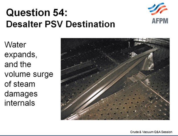
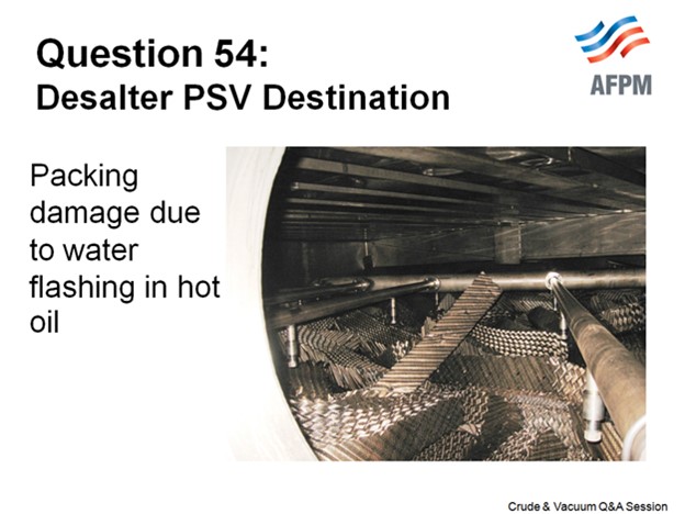
These are damaged stripping section trays, and the next slide shows damaged packing. The damage occurs when the water expands rapidly and there are huge uplift forces which damage the tower internals.
This slide is a generic crude preheat train to help us stay focused.

The best way to mitigate problems in your fractionator is by having an inherently safer design (ISD). The goal is to have a relief valve where only fire case relief protection is required. Within the code requirements, whenever you can lower your relief rates, you limit the amount of potential water carryover. Relief rates are very, very installation-specific and refiners are increasingly using and reviewing their control schemes, including review of their pump autostart philosophies (whether they have motors or turbines) to eliminate or reduce pressure surges that can lift the crude system relief valves.

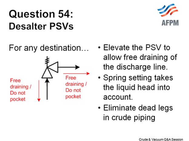
One important factor is that the crude piping (as well as the relief valve inlet and outlet piping) must never have dead legs or pockets where water can accumulate. This is important because these “puddles” of water can be “picked up” and carried with the bulk crude flow if there is a pressure surge, even if it does not lift the PSV. The water is accelerated through the flash drum and into the fractionator, causing damage like what occurs if the desalter PSV lifts and discharges to the fractionator. One refiner calls this the tsunami effect.
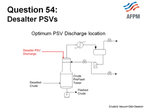
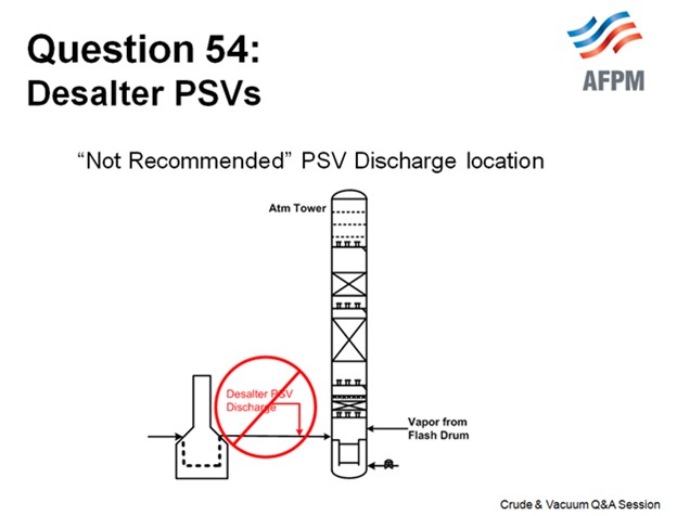
We think that the optimum location to route the PSV discharge is to the top of your crude preflash tower, if you have one. The top of the crude preflash tower acts like a mini flash drum, and the temperatures are cooler there; so, it is not going to flash quite as much or quite as hard as the main fractionator flash zone. Make sure that the routing is such that it is a top entry, so the line cannot fill with liquid and there are no restrictions in the outlet pipe.

An alternate destination, if you have a flash drum (and not a tower), is the inlet of the flash drum downstream of any backpressure control valve (if present). Not everyone has a backpressure control valve to suppress vaporization, but many people do. As before, the PSV discharge line must be a top-entry connection to the flash drum inlet line.

There are PSVs that discharge to the transfer line or into the main fractionator flash zone. This is not recommended (because of the potential damage that can occur); but if you have this installation in your facility, you can begin working to mitigate the relief load by making some changes that will mitigate the impact to your tower. These changes include elimination of dead legs, engineering changes to reduce the relief load enough to allow installation of a smaller PSV, and control changes to reduce the likelihood of pressure surges.
This slide shows some recommended reading. It is a paper that was published at a recent AIChE (American Institute of Chemical Engineers) meeting. It talks about pressure surge incidents, but it also includes quite a bit about relief valves and contains additional information.

ALLRED (Suncor Energy, Inc.)
I agree with Maureen. The issue here is the water when it expands. When you have liquid water hitting these high temperature crude units, they expand hundreds of times and can wreak havoc on your internals. I have personal experience with that. It was not a desalter relief but rather some condensate that was left in a stripping steam line. When it was turned on, the condensate hit the tower and just ripped out the trays; and these were beefed-up trays. So even if you have reinforced trays, when water hits, it can still cause a lot of damage. So, the best protection against this is to design your desalter such that the only viable relief case is fire.
We had a couple of desalters in one of our crude units that were redesigned a few years ago. When they were redesigned, we increased the design pressure enough so that fire was the only viable case. We then rerouted that PSV discharge to the flare knockout drum, so we did not have to worry about this issue. We have a couple of other crude units where the PSVs are still routed to preflash drums, much like Maureen discussed.
RATHINA SABAPATHI (Kuwait National Petroleum Company (KNPC)]
Good morning. The concern is related to this. Because of the safety valve location, there are dead pockets in the line more than 300 to 400 meters (about 1312.34 ft). And recently we had a failure on this line due to the corrosion which was due to the stagnant portion of the line. Is there anything that can be done?
In addition to the pocketing, some water vapor is still coming in and condensing (liquid), causing corrosion of the line between the safety valve and the desalter. Has anyone come across this issue? How do we overcome this?
PRICE (Fluor Corporation)
I just want to clarify that I understood you correctly. It is the inlet line to the relief valve that is elevated. Typically, the liquid line to the relief valve is liquid-filled, and it is filled with crude. I do not know where it is placed; but typically, there would not be water vapor that is making it up to this area.
RATHINA SABAPATHI (Kuwait National Petroleum Company (KNPC)]
It is not the water vapor. It is stagnant crude, plus a little amount of water which is causing localized corrosion because it is stagnant. It is in the inlet of the PSVs where we had two failures. Is anyone heating up this line or keeping it hot?
ALLRED (Suncor Energy, Inc.)
I have no experience with that.
PRICE (Fluor Corporation)
Thank you for the clarification. The PSV nozzle is presumably located on the top of the vessel. The inlet line runs vertically and is not pocketed but does have some long horizontal runs. Corrosion due to stagnant sour water is one possible cause. Another plausible explanation could be trapped gases from startup and/or the slow accumulation of gases [CO2 (carbon dioxide), H2S, etc.] that are evolving from the crude. The evolved gases could create a corrosive environment at or near the PSV inlet nozzle or in the piping. The following factors are to be considered:
-
The length of the inlet line that you note is substantial, and there are likely horizontal runs in the inlet line to the PSV.
-
The desalter operation will have a significant effect on the amount of water present in this line.
-
Some crude slates will evolve more gases than others.
-
Whether you have a method in which to ensure vaporization is suppressed in the crude (pressure control of the crude charge or back pressure valve at the flash drum).
-
If suppression of vaporization is not possible, then if the PSV has a bypass, you can periodically crack it open to purge any accumulation of vapor. Periodically cracking the bypass will also purge the stagnant crude in the line as well.
An additional resource is NACE Pub. 34109, “Crude Distillation Unit - Distillation Tower Overhead System Corrosion”, which include the following statements that may be relevant:
-
Page 7: Oxygen in the desalter washwater can cause increased corrosion in the desalter itself and in the CDU preheat train.
-
Page 23: Several sources of desalter washwater (e.g., city water, industrial water, surface water, and possibly vacuum tower overhead condensate) contain varying levels of oxygen. This oxygen can lead to pitting corrosion problems in the desalter washwater and effluent brine systems. Oxygen is also carried into the CDU distillation tower overhead systems by entrained water with the crude oil leaving the desalter. Besides causing pitting corrosion, oxygen can react with H2S to form elemental sulfur, which can cause fouling and/or corrosion. Oxygen can also react with sulfur to form acid gases such as SOx. Sulfur dioxide (SO2) and sulfur trioxide (SO3) are the precursors to formation of H2SO3 (sulfurous acid) and H2SO4 (sulfuric acid), respectively. The potential negative effects of oxygen are reduced by limiting the allowable amount of oxygen in the desalter washwater to less than 1 ppm. Oxygen scavengers are occasionally used to further limit oxygen’s effects. One user reported that he specifies a maximum oxygen concentration of 20 ppb (parts per billion) in the desalter washwater. When evaluating the use of an oxygenated water source for desalter wash, the benefits of increased washwater are normally weighed against the costs associated with corrosion, water purchase, and increased loading on the wastewater treatment plant.
LUIS GORDO (Amec Foster Wheeler)
Typically, desalter PSV relief is routed to the crude tower or preflash drum. Desalters may or may not be designed for the shutoff pressure of the cold crude charge pumps. It is generally a question of balancing the greater costs involved in designing for a high design pressure against the operational disadvantages caused by desalter safety valve occasionally lifting and not reseating properly during operational upsets. As a minimum, the desalters are always provided with a safety valve to protect against a fire case. If only designed for fire case, water damage should not be of concern. When the PSV is designed for a blocked-in case, mitigation steps should be taken, starting by designing crude or preflash tower internals to withstand increased uplift forces (2 psi minimum). Other strategies include:
-
Shutting off the water injection to the desalters and
-
Pinching back on the crude charge pump VFD (variable frequency drive) or turbine speed (if applicable)/shutdown pumps to reduce operational upset.
ANDREW SLOLEY (CH2M HILL)
Desalter PSVs may either release to a disposition inside the crude unit or outside the crude unit. Based on refinery surveys, the industry has nearly a 50/50 split of dispositions. A survey of crude units shows the following dispositions:

When the PSVs discharge to a downstream tower, they may either enter the tower flash zone or the tower liquid sump. In either case, trays should be mechanically strengthened to resist damage from flash vaporization of water.
The trend is to move away from discharge to blowdown systems without flares (flare-non-attached). Today these systems normally discharge to atmosphere through a blowdown drum.
MAUREEN PRICE (FLUOR)
The destination for the desalter relief valve discharge continues to be a good topic of discussion. Best Practices involve inherently safer design (ISD) where only fire case relief protection is required, and that resultant relief load will not result in liquid water to the fractionator.
Non-fire case overpressure protection is required when the mechanical design pressure of the desalter(s) is less than the achievable pressure during upsets, such as a blocked discharge. The magnitude of overpressure, relative to the code allowable, dictates the required relief valve capacity. Lower relief rates, as determined in accordance with code requirements, may reduce or avoid desalter water carryover and the severity of the upset.
Desalter relief valves, which can carry liquid water, have been a common cause of tray damage due to the sudden expansion of any water present.
Discharge of the desalter PSVs are commonly routed to the following locations:
The Atmospheric Tower Flash Zone: It is not recommended to route the desalter PSVs to the atmospheric tower unless the only case is fire protection, although there is at least one Southern California refinery that has the desalter PSVs discharging to a common header that connects to the transfer line.
A Dedicated Blowdown Drum to Collect Liquid PSV Discharge Streams: A dedicated blowdown drum (VENTED TO A CLOSED FLARE SYSTEM) is the safest option with the least impact on unit operations during a relieving scenario but has the highest capital cost due to the large size required.
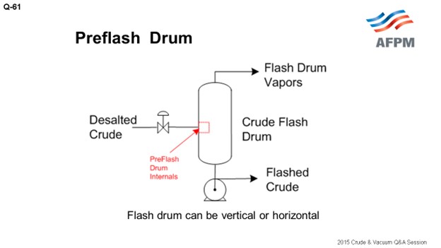
A Preflash Drum: Discharging a preflash drum is considered an optimal solution. It is lower cost since there frequently is already a flash drum; it is a minimal operational upset scenario as the drum contains enough volume for water vapor to flash without a sudden surge in pressure; there is already a pump to allow emptying of the relief liquids; and, the downstream exchangers will ensure the gradual heating of the desalter liquids (which will likely contain water at some point) by the preheat exchangers to avoid sudden water vaporization.
The Preflash Tower: Discharging the desalter PSVs to a preflash tower is acceptable; provided that the discharge is to the upper section of the tower, there should be no problem with tray uplift. Discharging to the flash zone carries the same risk of tray uplift as routing to the atmospheric tower flash zone.
Other key design parameters to mitigate operational concerns are that:
-
The desalter PSV inlet and outlet lines are free-draining (not pocketed) to ensure that liquids cannot accumulate anywhere;
-
The entire crude preheat system is designed without dead legs so that water cannot accumulate anywhere;
-
Appropriate flow and/or pressure control of the crude charge to the unit;
-
Operational review is performed on the Autostart controls on spare charge pumps and the use of variable speed drives (turbine or motor).
Fluor recommends the following paper as an excellent reference on the subject: “More Tower Damages Caused by Water-Induced Pressure Surge: Unprecedented Sequences of Events”1, which is a classic on the subject. It presents the case studies and the lessons learned, as well as several recommendations which we endorse.
Year
2015
Process
Question 61: What are the advantages and disadvantages of preflash/pre-topping columns in crude units in terms of operational flexibility to process different API crudes? Please comment on overall energy efficiency and reliability (corrosion).
ALLRED (Suncor Energy, Inc.)
At our refinery in Commerce City, we have three separate crude units. One crude unit has a classic preflash drum with the vapor going to the flash zone in the atmospheric tower, which is very typical, as shown on the drawing.
Another one of our crude units has a preflash tower with its own independent reflux system. The advantage here is not shown on this drawing, but you can have a side-draw of light liquid products.

Our third unit has a very convoluted arrangement. I am not going to show any drawings of it. It is an old unit that has evolved in a very unique way, but it has what we could call a preflash tower. It has a single overhead reflux that is combined with the atmospheric tower. The atmospheric tower overhead vapor comes back into the middle of this preflash drum. You would never design a unit like this today, but it is an older unit that evolved that way.
Preflash drums are useful for removing the vapor from the feed to the atmospheric tower, but there is a lot of debate about its purpose. Many people believe that this is done for energy purposes, but I think those who really study this come to the realization that it is not for energy. You are doing it for hydraulic reasons. You are trying to get the vapor out of the piping without having larger furnace tubes and piping hydraulically going to the atmospheric tower.
In theory, the optimal location to send the vapor is the spot on the atmospheric tower that most closely matches what that vapor looks like. But in practice, that can lead to a lot of problems because foaming is the biggest problem in preflash systems. It is not really a matter of “if” it is occurring; but rather, to what degree it is occurring. Have you designed your systems adequately to make sure you are not getting a lot of foaming that then hits your tower? If so, then the reason people send preflash vapors to the flash zone is so that the black products, which end up in that vapor, will not contaminate your lighter side-draws. Some people put in vortex clusters to knock out the foam. I have no experience with them, but I understand they can be effective.
The advantage, as I mentioned before, of having a preflash column is that you can have your own overhead reflux vapor recovery system. You can then take some liquid drawn off the side of that tower and recover some product. If it is adequately sized, you can still manage your issues with foaming and sulfur. There is a really good, detailed discussion on foaming and preflash systems, drums, and columns in Question 62 of the 2012 AFPM Q&A.
Another option is a hybrid that uses liquid from the atmospheric tower reflux to the preflash column. I am not very familiar with this option, but I read about it in the recent Petroleum Technology Quarterly. The article claims that energy efficiency is much improved in this arrangement from a typical preflash column.10 The claim seems plausible. Technically, the bottom line for corrosion, operability, and flexibility is that you just need to understand that the size your crude range needs to be in order to adequately allow for the flexibility you need.
PRICE (Fluor Corporation)
I echo everything Bruce already said, and I want to add a couple points. Sometimes you can debottleneck a unit by 10 or 20% with a light crude by adding a preflash tower. It can be energy-efficient; but equally important, as Bruce noted it, it debottlenecks the flashed crude preheat train and the heater.
However, a preflash tower is not always energy-efficient; but sometimes, it does end up that way! The energy savings associated with the addition of a preflash tower depends on the location of the heat transfer surface area, what cutpoints you are after, and which piping and controls you have to work with. One of the other benefits we see with a preflash tower is that by removing the light paraffins (and by light, I am talking about C5 and lighter), you can significantly reduce the asphaltene precipitation and fouling in the downstream exchangers.

When you do add in a preflash tower as a revamp, consider the fact that you will significantly change the vapor traffic in the atmospheric tower unless you compensate somehow by either increasing your stripping steam, lowering your pressure, or having a higher heater outlet temperature. The light gases being taken out in the preflash tower actually do have a stripping effect and will increase your diesel yield. This stripping effect is sometimes small, but you do actually need to check and make sure you understand the impact.
The other consideration is that the water dew point in the preflash and atmospheric tower will change based on the crudes you are running. This is very important. Watch your overhead temperatures to ensure that you have adequate margin above the water dew point in all operating scenarios.
The last comment is that if you have a highly variable crude slate with a significant crude gravity range, it will add some complexity to the design. Designing for a crude slate with a wide range of gravities is doable (safely and reliably), but you do need to understand the parameters up front.
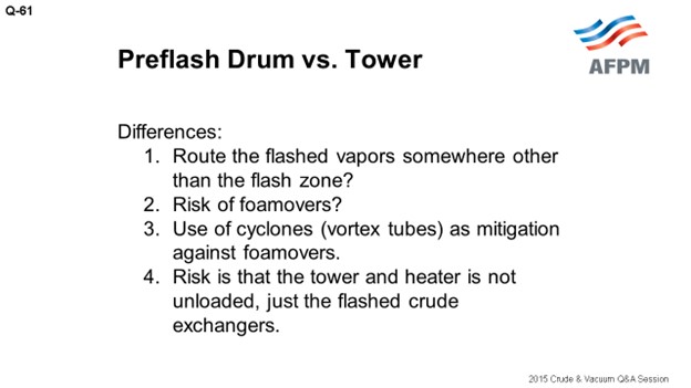
As Bruce said, if you just have a flash drum, you really need to be bold to route the flashed vapor somewhere other than the atmospheric tower flash zone. Routing the vapor directly to the atmospheric tower flash zone will debottleneck your flashed crude preheat exchangers; however, the flashed vapor has a tail (heavy end distillation) due to the single-stage nature of this drum.
With respect to the risk of foamovers, they happen. A properly sized drum will help mitigate them, as will the use of some sort of cyclones or vortex internals. Equally important is that whatever you have must be instrumented well, so you will know what to watch to maintain an upper hand and manage any foaming problem when it happens. You need to have instrumentation to watch your pressure, levels, and flow rate in the flashed crude. You will see, depending on the instrumentation in your unit, the indications come up (hopefully) before the foaming hits the main fractionator.
NAGASHYAM APPALLA (Reliance Industries Ltd.)
What is the Best Practice for monitoring the foaming incidence in the flash drum?
ALLRED (Suncor Energy, Inc.)
It is important to monitor the color on your products on the side drawer of the preflash tower because that is where you will see it first.
PRICE (Fluor Corporation)
We encourage people to watch for instability in their flashed crude flow rate, in the level, and in the pressure, as well as watching your pump for cavitation. We feel like that is where you will see it first.
CELSO PAJARO (Sulzer Chemtech USA, Inc.)
Just to clarify, if the preflash has a level glass gauge, you should see the foam there. The second point is that we have designed vortex tubes for preflash columns and preflash drums, and they work well. On our website, we have a video showing how it works. You can see how the foam is reduced between having nothing and just adding the foam-breaking element.
HAROLD EGGERT (Athlon Solutions)
You can also install a TI (temperature indicator) on the vapor out of that flash drum and watch the temperature. The temperature will change as you see increased foaming. The second part of this question is a commercial for this afternoon’s Principles & Practices session. There will be a session discussing Best Practices for caustic injection, and there are some interesting phenomena around the foaming in a flash drum, depending on where you put in the caustic for chloride suppression. So I encourage everyone to come to the P&P session this afternoon.
ANDREW SLOLEY (CH2M Hill)
If you are going to have a nuclear-level device in one place in a refinery, it would be on the preflash drum or tower bottoms. Some type of radiation instrument for online density and level measurement will greatly improve performance. There are other ways to monitor the foam level. But in these situations, by the time you notice it using other methods, the foaming event has already occurred. This is one place to spend money to make sure that if a foaming event happens, you will be able to react to it in real-time to prevent foam from entering the crude column.
LUIS GORDO (Amec Foster Wheeler)
Increasing diluted bitumen, synthetic crudes, and tight oil crude components in the feed increases the amount of light material that must be processed through the refinery (higher API feed). Depending on how the crude diet changes, the increase in light materials can be significant. This is often one of the limits to leveraging the typically discounted pricing of domestic tight oil.
Many refiners find that their ability to blend light tight oils into their feedstocks is restricted by the higher content of light materials [LPG (liquefied petroleum gas) and naphtha] in the crude. Preflash towers offer the advantage of debottlenecking crude preheat trains and atmospheric tower overhead sections in order to enable higher volumes of crude to be processed. Typically, preflash towers should be located after the desalter in order to mitigate corrosion/fouling. This spot is also convenient as a crude booster pump is almost always required at this location. Foaming is a concern for the design and operation of preflash towers/drums. Superficial liquid velocity must be kept below a certain threshold. Specific internals, such as vortex clusters that separate liquid and vapor by means of centrifugal force, can be considered. If the preflash tower is equipped with distillation trays/top reflux, there is a reduction in crude preheat temperature that must be offset by the crude heater.
In addition, if there is a plan to process heavy crudes also, then preflash towers need to be evaluated for the same due to lower light end loads. If this flexibility is required, then a preflash drum may be a better choice.
Economics that come into play are:
-
Increased Profit through incremental unit throughput,
-
Operating Expense of preflash tower condenser and pumps versus furnace firing cost, and
-
Capital Expense including modification of hot preheat train, crude tower overhead, and possibly furnace tubes versus new preflash tower, condenser, overhead drum, and pumps.
ANDREW SLOLEY (CH2M HILL)
Preflash drums and towers are a relatively complex subject. For revamping an existing unit, the addition of either may help the plant by relieving specific equipment constraints. The successful addition of a preflash unit requires a detailed knowledge of the existing equipment limits which requires a detailed analysis of unit performance based on validated plant data from test runs. No neat guidelines exist for general rules when adding a preflash when specific and complex constraints are involved.
For new units, specific situations merit preflashes. Having a preflash will generally allow for more flexibility to move toward both very light (45+ API° gravity) and very heavy (20- API° gravity). Specific examples where preflashes help unit flexibility are:
-
Very light crudes, limits on heater outlet vaporization: Recovery of very light crudes can be limited by heater outlet vaporization. Excessive vaporization can increase heater coking rates due to low liquid irrigation of the heater outlet tubes. A preflash removes some of the vapor, increasing liquid fraction at the atmospheric heater outlet.
-
Crude blends, asphaltene precipitation: A preflash can selectively remove C5- material from the crude. This may reduce asphaltene precipitation when processing a blend of light crude-heavy crude.
-
Aggressive heat integration, high heater inlet temperatures: A preflash may allow for lower inlet pressures to the fired heater when heat integration is very aggressive. This would be likely when running light crudes over a 525°F inlet temperature or heavy crudes over a 565°F inlet temperature. With current gas pricing in North America, highly aggressive preheat train outlet temperatures are typically not economical. However, the economic basis is different for many European or Asian refiners. Heat integration with extremely light crudes may benefit from a preflash at temperatures below 525°F.
-
Heavy crudes, desalter water removal: With heavy crudes, the desalter may leave a significant amount of water in the crude. A preflash may act as a dehydrator (water vaporizer) upstream of the hot train.
In general, preflash drums have a minimal impact on unit corrosion. They may marginally reduce salt hydrolysis by drying the oil. However, the change is small.
Preflash towers that have separate overhead systems from the crude distillation tower significantly increase atmospheric tower overhead corrosion problems. The preflash tower removes light ends from the atmospheric tower feed. This greatly increases water partial pressure in the atmospheric tower overhead, making aqueous chloride corrosion more severe. The increased corrosion normally holds true even if the removal of light material changes the atmospheric tower pressure profile.
For existing units, adding a preflash drum or preflash tower nearly always makes the unit less energy-efficient. Exceptions include when the unit has a very low atmospheric heater inlet pressure that limits heat integration or if vaporization in the preheat train is already creating large pressure drops.
For new units, the situation is ambiguous. On a constant return basis, adding a preflash tower may either increase or decrease energy efficiency. The result depends upon targeted crude preheat temperature, crude vaporization, crude gravity, preflash type, cost of firing versus cost of steam, product temperature to downstream units, and other factors.
BRUCE ALLRED (Suncor Energy U.S.A.)
At the Suncor Commerce City refinery in Colorado, we have three crude units with three separate preflash configurations. One crude unit has a typical preflash drum with overhead vapor going to the atmospheric tower flash-zone; one unit has a preflash column with an independent overhead condenser and reflux system and a side-cut draw; and, the other crude unit has a unique, convoluted quasi-preflash tower with a single overhead condenser and reflux system which also handles vapor from that atmospheric column that vents back to the middle of the preflash column. Each of these systems has their unique characteristics and limitations.
Preflash drums are useful for removing vapor from the feed to the atmospheric tower furnace. This is done to reduce unnecessary heat absorption into material that is already vaporized and to eliminate difficulties that can be encountered in control valves which would see two-phase flow, particularly in a multi-pass furnace. The use of a flash drum reduces process piping and furnace size due to the lessening of two-phase flow hydraulics. In theory, the optimal location to send the vapor is to the spot on the atmospheric column that most closely matches the vapor steam. However, the reality is that most refineries with preflash drums send the vapor to the flash zone. This is done since preflash drums can be prone to have foaming and carryover of heavier liquid, which puts reduced crude in locations not designed for reduced crude. This leads not only to dark light oil products, but it can also put sulfur or naphthenic acid into places that were not designed for it. The downside to sending the vapor to the flash zone is that the vapor will quench the temperature in the flash zone, so the furnace outlet temperature must be set to compensate. Since the drum, overhead line, and furnace sizes are already fixed in a refinery, there is limited flexibility for opportunity crudes unless the sizing of these components allows for the changes in flow hydraulics, heat transfer, etc.
A preflash column can be a better option if it has its own reflux and vapor recovery. It allows for a side draw of light products and, if adequately sized, may provide flexibility for variable API feeds depending on loading and turndown. The downside to a preflash column is the money required to build, maintain, and operate a separate overhead reflux system. And also, just like a preflash drum, you need to watch out for foaming in the tower and low velocities in furnace tubes, which may cause premature coking of the furnace tubes. If much lighter crude is run, the preflash tower may be too small and still be susceptible to foaming and liquid carryover. For more detailed discussions on foaming in preflash drums and columns, see Question 61 in the 2012 AFPM Q&A Answer Book.
Another option that was highlighted in a recent publication11 has a hybrid option that uses liquid from the atmospheric tower reflux to the preflash column. This article claims that energy efficiency of this arrangement is superior to both the preflash drum and preflash tower arrangements. I have no experience with this hybrid option, but the claim seems plausible.
We have not seen severe problems with foaming any of our three crude units; but if a crude slate that is dramatically different from the normal slate that is fed to one of the units, we have to monitor closely for any signs of flooding or accelerated fouling.
The bottom line is that preflash drums and columns can add flexibility in running opportunity crudes but only to within the limits to which these components are designed.
Having a preflash drum or column increases energy efficiency with removal of the lighter components in the crude to reduce operating pressure/pressure drop requirement in the preheat exchanger train and to reduce furnace duty requirement. However, the reduction of the lighter components with the preflash system will also decreases the amount of flashed vapor in the atmospheric flash zone, which will need to be compensated by increasing the crude heater coil outlet temperature and/or crude tower bottom stripping steam flow. With light crudes, typically a 10 to 20% debottleneck can be achieved in the atmospheric tower, heater, and condenser.
With a preflash drum (as opposed to a preflash tower), the overhead is usually routed into the flash zone for fear of foamovers contaminating products, and the resulting upsets in downstream units. Cyclone separators (also known as vortex tubes/clusters) in the preflash drum are effective against foamovers, but one foamover that gets away from the cyclones causes so much mess, product loss, catalyst poisoning, and economic loss that most refiners shy away and route the overhead of flash drums into the flash zone. When this happens, there is zero unloading of the heater and the tower.
The preflash tower (as distinct from the drum) enables the refiner to recover naphtha (and sometimes jet fuel) that completely bypass the main atmospheric tower. A well-designed preflash tower has a pressure drop measurement and other warning instrumentation that can see a foamover before it gets into the product. The preflash tower also provides a venue for discharging the desalter relief valve without causing tray damage. However, the drawback of a preflash tower is a reduced diesel yield in the atmospheric tower because the light ends help with the stripping of the crude. This effect is usually small but needs consideration. Additionally, with some of the naphtha removed upstream, it can drive the atmospheric tower into a water dew point limitation. This may constrain the amount of stripping steam that can be used and therefore the diesel recovery. (Note that the effect of the higher naphtha boiling point is higher, and reduction in off gases may counter the water dew point issue. You have to study it to be sure.)
Another advantage of using a preflash drum (or a preflash tower) is the removal of light paraffins (C5 minus) which can reduce downstream asphaltene precipitation and fouling.
Year
2015
Process
Question 42: What water sources are you using for desalter waterwash, and what are the advantages and disadvantages of each? What role does desalter waterwash source and injection location play in desalter performance?
SOLOMON (Athlon Solutions)
As Gordon said, these were throwback questions that Chris McDowell answered a while ago. It would have been great to see those actual answers. I am sure they are very similar to what we have now; but still, just to see how much the desalting process may or may not have changed.
In the years that some of my other colleagues and I have been working on desalter waterwash practices, we have some Best Practices we think work well with all varieties of crude. First is wash water. Yes, wash water. More wash water: whatever you can get. Typically, 5 to 8% of the crude charge is what we recommend. Heavy crudes may be even a little higher, if we can get it.
Wash water quality is also another very important aspect. We look for wash water somewhere between 6 and 8, in terms of pH, which contains less than 50 ppm of ammonia; is low in chlorides; and, has low hardness, low oil content, and – obviously – low oxygen content.
Preferred sources: There are a variety of sources we like to see. Stripped sour water is usually our best source. Sour water from the overhead systems, such as the vacuum overhead, is very good, too, as are non-scaling freshwater and steam condensate. Steam condensate is obviously an expensive alternative, but it can be used.
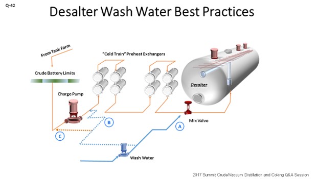
Over the years, we have experimented in a technical sense and looked at different ways of injecting wash water. What we found, at least at Athlon, is that we try to get as much of the wash water upstream as possible. This is actually upstream of the crude charge pump. We want to get some very good mixing and improve our contact time. After that, just a little ahead of the crude preheat is the next best source. Finally, at the mix valve where we typically see a problem is that when we inject water and chemical at the mix valve, and we just do not have a lot of contact time. I cannot tell you how many operations I have seen where, well, the mix valve really is not the mix valve. It is a control valve or something else; or it is wide open. So, inject wash water as far upstream as possible.
There are some advantages of the different sources of overhead water. Vacuum overhead tends to be fairly light in hydrocarbons and low in pH, but there are some disadvantages as well. It can result in recycling of any tramp amines that are in the system, so we want to be careful of that.
These are some pictures of basically what is going on, in terms of crude oil and then desalted crude. In the picture on the very left, we see raw crude – just filtered with toluene and not washed with water – containing about 85.5 ptb (pounds per 1,000 barrels) of salt. You can see those crystalline forms. The top right photo shows what happens when we do it just ahead of the desalter. At that point, you still start to see some good work. We are getting most of the salts out, but still about 3.5 ptb remains there. Finally, what we have seen when we move it into the suction of the charge pump is that, again, we have 0.9 ptb. We are contacting a lot of the salts and really doing a good job removing them in the water.
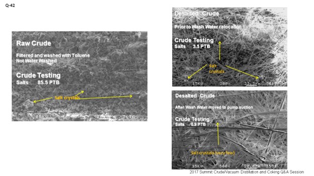
Some people might say, “Well, are we creating a very stable emulsion by doing that?” That is a possibility; it can happen. But crude charge pumps tend to be good devices for moving fluid and not necessarily very high shear mixing apparatus; so, most of the time, we are seeing very good results from this operation.
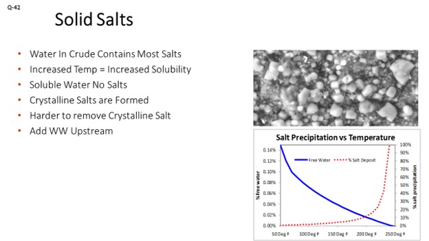
Sometimes we have talked about water that is soluble in the oil. When that happens, though, just the water goes into the oil. The salts stay behind and end up in this more crystalline form. We want to be careful that we are not getting a lot of the soluble water out of the crude and just leaving salts behind; because by that time, we have already lost the opportunity to contact the salt and get it out of the system. That is why we try to continue to move it as far upstream of the water injection as possible. The pictograph below shows the solid salts that can be left behind in the crude oil.
So, those are basically the Best Practices. I do not think they have changed in a long time, since Chris gave the response several years ago. It would have been great to have some of the throwback response, but perhaps the next time.

LÉGARÉ (Andeavor Martinez Refinery)
I do not really have much to add after that discussion. I will say, though, that is there is a difference between what is ideal – as far as makeup wash water is concerned – and what you actually get in a refinery. So, it is probably best to put some thought into how you are going to mitigate your deficiencies in your gaps, as far as pH and ammonia content are concerned. One of the techniques we have looked at in the past is acidifying the wash water to deal with high amounts of ammonia. That technique has been effective for us in the past.
Hydraulic limits: If you are trying to get your stripped foul water over to a crude unit and the sources are not close by, then those hydraulic limits can also limit the amount of makeup you have at the desalters. It becomes a juggling act between what you have and what you would like to have. Then, you have to come up with the proper justification to put in these new projects or new facilities to move forward to get closer to Best Practice.
BILL CATES (Hunt Refining Company)
One subject the panelists did not discuss, which is one of our considerations, is wash water percentage. One of the ways to get it up is to do recycle off the bottom of the desalter. There are pros and cons to that method; because obviously, the water is hot. The other fact is that it actually contains some salt; meaning, it has a heavier density, which helps the water get it back out. Very seldom are you super-saturated with that amount of salt. So, do you have any comments about using recycle to supplement wash water in front of the mix valve?
SOLOMON (Athlon Solutions)
Just like Eric said, usually what you have to use is what you can get. Certainly, we have seen recycled wash water. Of course, we have a two-stage of desalting that is always occurring. Yes, you just have to be careful. Use the best quality. But often, as Eric mentioned, you just use what you have there.
KEVIN SOLOMON (Athlon Solutions)
Wash Water Best Practices
Over the years, we have established several Best Practices concerning desalter wash water rates, quality, injection locations, and sources that – when utilized – help ensure optimum crude oil desalting.
We have found that wash water rates of 5 to 8% of crude charge is sufficient for light- to mid-API crudes and that heavier crude need slightly higher rates. Wash water quality is equally as important as wash water rates. Ideal wash water specifications are:
-
pH level of 6 to 8,
-
Contain less than 50 ppm ammonia,
-
Contain less than 50 ppm chlorides, and
-
Have low hardness, low oil content, and low oxygen content.
Our preferred wash water sources are stripped sour water, sour water from overhead systems (such as vacuum overhead condensate), and non-scaling fresh water and steam condensate. The advantages of overhead water are:
-
It removes light hydrocarbons from the vacuum overhead water (less hydrocarbons to sour water stripper), and
-
The lower pH helps lower total wash water pH, especially if there is a higher pH wash water source in use.
The disadvantages of atmospheric or vacuum overhead water are that there is the possibility of recycling tramp amines back into crude oil.
The location of wash water injection is also important. Our Best Practice is to inject wash water far upstream of the desalters to provide sufficient time to contact any water (and thereby salt) in the crude oil. Our preferred injection points (in order of preference) are:
-
At the suction to the crude charge pump,
-
Ahead of the pretreat train, and
-
Ahead of the mix valve.
There are several advantages to injecting wash water ahead of the crude charge pump. First is the improved contact of wash water with crude oil, thereby improving desalting. Injecting ahead of the preheat helps to heat up desalter wash water, which minimizes formation of crystalline salts in cold preheat train and therefore results in less fouling and higher desalter temperature. This injection location can permit running desalter mix valve lower with equal or better desalter salt removal; hence, lower desalter pressure which – in some instances – can lead to slightly higher crude throughput.
There are some disadvantages of injecting wash water upstream of crude charge pump. It is possible that the increased shear stress resulting from the pump can create a tighter emulsion in some cases. Without the right EB and low oil/water residence time, this emulsion may be hard to resolve. If the desalter wash water is coming from the second stage, it will be 250°F, which will then be injected into the cold crude. On a single-stage, the brine water exchanger never gets the feed water up to desalter temperature; so, it is not as bad a problem. Using cold, fresh water as part of the charge pump wash water can help, even if only a portion of the total water is going to the pump suction.
ERIC LÉGARÉ (Andeavor Martinez Refinery)
Stripped sour water is commonly used as makeup water to a desalter. Disadvantages of stripped foul water include NH3 in the wash water as it can cycle up and increase the risk of chloride salts in your tower/overhead system at high pH levels. Acidifying wash water with high NH3 content can be a solution to reduce the partitioning of NH3 into the crude phase. The advantage of this water source are the high volumes available at low cost as this stream is normally routed to the wastewater plant.
Alternatives would be condensate from the atmospheric or vacuum fractionator overhead systems. The advantages of this stream are both its availability and proximity to the desalter. The disadvantage would be the chloride salt content in this water stream, if there was no supplemental waterwash in this system, pH, and the increased potential for amines.
Injection of wash water goes to the second stage of a two-stage system. Alternately, some or all of the water can also be injected upstream the mix valve to maximize mixing with the crude upstream of the desalters.
CHRIS CLAESEN (NALCO Champion)
The best desalter wash water sources are stripped sour water with low salt and solids content or BFW, but this material is expensive. Try to avoid waters containing oxygen, hardness, tramp amine, and high salt levels. Water injection location has a significant impact when very low salt levels are required. Injecting part of the water in the cold preheat will help remove some of the crystalline salt and prevent drying out of the crude. The amount of water that needs to be injected at each specific location will depend on the unit design and the feed properties.
DENNIS HAYNES (NALCO Champion)
The list of potential desalter wash water sources is long. An important factor to consider when choosing a source is to review which contaminants are in the water. Oxygenated sources, such as industrial water, may cause an increase in SOx to the distillation column. Stripped sour water is a common source and has been used effectively in many cases; yet, caution is needed when the pH is high, especially if the pH is due to caustic addition at the SWS. Atmospheric column overhead water may or may not be acceptable, depending on the amine content and the pH of the desalter wash water blend. Vacuum overhead hotwell water is typically a good source; yet it needs to be monitored to make sure it does not bring a large amount of emulsified hydrocarbon condensate to the desalter. Moderate to slightly lower pH wash water typically results in better emulsion resolution and contaminant removal. Injection of wash water to points that facilitate good yet controlled mixing will also result in better contaminant removal. Each system needs to be optimized based on feed quality and characteristics and system mechanical design characteristics.
PHIL THORNTHWAITE (NALCO Champion)
The provision of adequate, good quality desalter wash water can present a significant challenge to some refineries; some sources of water are good, and some not so good. Utilizing poor quality wash water can result in processing issues, contributing to desalter upsets, corrosion, fouling, and wastewater treatment plant issues. So, the choice of the water source is critical to good desalter performance. Ultimately, the best way to identify whether a water source can be added to the desalter wash water is to analyze the contaminants that are present in that particular source and in the overall wash water charge, followed by an assessment of the risk that these incur.
The best water sources, and the ones more commonly utilized, are overhead sour waters from the crude and vacuum units and good quality stripped sour water. There are considerations, though, in that the amine content of the overhead sour waters, whether it be from neutralizers or tramp amines, should not present an amine recycle risk that could increase the risks of salt formation. Likewise, the amine content of the VDU sour water should be considered, as well as well the level of hydrocarbons in this stream, as this can potentially lead to desalter upsets and/or impact on desalter effluent quality. If stripped sour waters are used, ideally, they should be low in ammonia and also phenols, while bottoms from an SWS that injects caustic to increase ammonia stripping is best avoided. High ammonia levels can elevate the pH of the water that can increase emulsion formation; and depending on the pH, it will readily partition into the oil phase, passing to the crude unit overheads where it can increase the risk of salt formation. Phenols can impact on effluent water quality and have a huge detrimental impact on the secondary processes of the wastewater treatment plant, while they can also contribute to emulsion formation and stabilization.
For those refiners limited in the amount of wash water available, a brine recycle can be an effective means of boosting available wash water and improving desalter performance. However, care has to be taken when utilizing desalter brine in this way; if there is a deterioration in effluent water quality, recycling this stream can precipitate a much larger desalter upset.
With respect to wash water injection locations, it is typical to inject a portion of the total wash water in front of the cold preheat exchangers with the remainder just before the mix valve. The portion injected before the cold preheat dilutes the scaling salts present in the crude, reducing the risk of exchanger fouling. However, varying the ratio of water injected at these two locations can improve salt removal since the cold preheat exchangers can help improve mixing with dispersed brine droplets and potentially crystalline salts. This ratio can be easily determined through a desalter optimization study using the correct analytical methodology.
GLEN SCATTERGOOD (NALCO Champion)
We use primarily stripped sour water along with vacuum overhead condensate. Ammonia content of the stripped sour water must be controlled in order to manage the combined wash water pH. An elevated wash water pH is caused by increased ammonia in the stripped sour water, which lead to degraded dehydration of the desalted crude inside the desalter vessel.
We use stripped sour water as the source for desalter wash water. A brine recycle is in place to increase the total wash water volume greater than 7% based on crude charge. The addition of the recycle and increase in total wash water has reduced atmospheric distillation tower overhead chlorides by 20%.
SAM LORDO (NALCO Champion)
The typical desalter wash water sources are:
-
Stripped sour water and
-
Condensates.
The typical desalter wash water quality is:
|
pH |
6-8 |
|
NH3 |
< 10 ppm |
|
Cl- |
< 25 ppm |
|
Temperature |
> 180°F (82°C) |
|
Oil |
Nil |
|
Oxygen |
ppb (parts per billion) |
Stripped sour water tends to run high in pH and ammonia. The high pH increases the potential to stabilize emulsions. It is also possible that the stripped sour water could have other contaminates present, like cyanide, organic acids, and amines (tramp and internally generated).
Condensates from the CDU tend to be better to use overall; however, they, too, can contain amines (from neutralizers being applied and from crude oil sources, organic acids, H2S, ammonia, etc.) Condensates from other units – like delayed cokers, fluid catalytic crackers (FCCs), hydroprocessing unit stabilizer/stripper towers, etc. – can introduce other contaminates not normally found in the CDU or they can increase the concentration of other contaminates. For example, an FCC condensate can easily have more than 2,000 to 4,000 ppm ammonia present, compared to a typical CDU overhead of 40 to 100 ppm.
Solids, high pH, and other contaminates present in the wash water can result in the stabilization of desalter emulsions or can change the solubility of contaminates in crude oil, which could result in unwanted contaminates going out of the desalter to the downstream equipment.
Year
2017
Process
Question 70: Electrostatic precipitator (ESP) fines handling is often complicated by fluidization and mechanical integrity issues. How often do you experience these types of fines handling issues, and what are some of your Best Practices to successfully mitigate these issues? What are your Best Practices for safe fines withdrawal from the ESP?
FOOTE (CHS Inc.)
Unreliable ESP dumping can lead to shorting out of the transformer rectifiers and the associated missions troubled by losing a cell of your ESP. Also, inconsistent dumping can put operators directly in harm’s way just since they are not consistent in the way they dump; and then indirectly, if the dumping leads to unit shutdown which will expose them during the shutdown. So, reliable operation of those hoppers is important.
At CHS, we have two dry ESPs on both of our operating units. We have not really noticed a difference. That catalyst morphology has much to do with whether they dump or not; but it is an unrefined operation, so I cannot really speak about it. What I can tell you is that as you let the catalyst accumulate in that hopper, it forms an insulating barrier. The thicker that insulating barrier gets, the more chance you will have for a temperature gradient across that barrier to be less than the bulk temperature of the ESP. So, as you let it build, the likelihood of condensation increases dramatically. Condensation is the leading cause of catalyst hopper issues.
Now I will talk about the importance of proper design and operation of ESP hoppers to ensure that they dump correctly. Insulation is important on your hoppers. Pay very close attention to manufacturer’s recommendations around the corners. The contractors will often get that wrong. Also, check that the heater grids are properly installed: the strike plates, level indicators (typically nuclear), and vibrators you use for evacuating the hopper. We also have fluffing nitrogen connections above the knife gate valves that may help get catalyst moving. We have never used them, but they are there.
Regarding the operation, do not let catalyst accumulate in the hopper. Empty each hopper early and often; and when there is an upset, empty the hopper more often. You cannot do it enough. Pay attention to the sensory indicators. A good operator can tell if the hopper is empty or not if it is not rattling right. Utilize strike plates to hear the difference between the sound of an empty drum and a full one. Next, monitor those hopper temperatures; and then, do grid checks. These hopper heater grids have multiple patches. You can lose one patch and have a cold spot, so make sure you are checking each one of those grids on a regular interval: maybe quarterly. I think we do ours every six months. We check those grids to ensure they are working right before the winter hits, because they can short out. We have lost patches and been able to catch it that way. The bulk temperature of ESP inlet at 425°F or greater. If you are too aggressive on your sootblowing activities for your waste heat boiler, sometimes you will get that temperature a little too cold. The ESP does not perform well when the flue gas is too cold.
DINKEL [Marathon Petroleum Corporation (MPC)]
I agree with Darin’s points about making sure your hopper heaters are working and not allowing the hoppers to back up. I will add a strategy we use internally. One of the newer units is doing biannual PM (particulate matter) audits with the manufacturer coming in to perform a complete review of the ESP, including looking at all the cells and basically going through and tuning the cells to optimize performance. On an older unit that we just retired last year, we got to the point where we were doing quarterly audits on it to make sure we could maintain our environmental compliance.
FEDERSPIEL (W.R. Grace & Co.)
We looked at what could be complicating fines handling out of an ESP. We might be able to break that down into some mechanical integrity issues where it is possible that internal abrasion is impacting your ability to offload due to long-term operation. If the valve fittings were misaligned due to thermal cycling, or if catalyst particles fouled the seats of the valve guides, then that might also impact your ability to withdraw the catalyst. I think this is the first time the panelists are going to disagree. I get to say that catalyst PSD (particle size distribution) and morphology, I believe, do play a role in the ability to move those fines material out just by the fact that an irregularly shaped particle has a higher surface area. And because these are fines, you know the surface area-to-mass ratio is a little higher and gets a little more cohesive as we increase that surface area to mass ratio.
The last part of the question is about safe handling. Using proper PPE (personal protective equipment) is going to include goggles and a face mask. Also, make sure you are properly grounded before any operators to do anything with the ESP.

MICHAEL FEDERSPIEL (W.R. Grace & Co.)
Electrostatic precipitators (ESPs) represent an effective medium for particulate emissions control and are, therefore, commonly used within the FCC industry, especially in North America. Although ESPs are not designed to capture all of the catalyst particles present in the regenerator flue gas, they usually exhibit sufficient performance to successfully reduce the particulate content in the flue gas below 50 mg/Nm3. As the question suggests, fluidization and mechanical integrity issues can significantly hinder the withdrawal and handling activities of catalyst fines.
With respect to mechanical integrity, the most common issues correspond to malfunctioning catalyst discharge valves to the collection hoppers due to any of the following causes, among others:
- Internal abrasion throughout long-term operation,
- Misalignment of the valve fittings due to thermal cycling, and/or
- Fouling seats or guides due to catalyst particle deposits.
The electrode and collection plate rappers can also experience mechanical integrity issues that can significantly hinder catalyst withdrawal efficiency. These mechanical rappers help maximize the recovery of the ESP fines while properly preserving electrode efficiency and performance throughout long-term operation. Complete failure, or suppressed performance of these rappers, generally reduces the number of fines withdrawn from the system at constant particulate loadings and can significantly shift the particle size distribution (PSD) of the withdrawn fines towards a coarser profile. The reduced capability of withdrawing fines is usually accompanied by gradual increases in particulate emissions at the stack beyond the normal or allowable ranges. The mechanical integrity of the rappers can be affected by thermal cycling over time, as well as fouling issues stemming from the ingress of fines.
Operating conditions also influence the mechanical integrity of the ESP. Sudden thermal cycles, such as those associated with an emergency trip of the unit or sudden bypass of the ESP train, can increase the threat of mechanical integrity deficiencies associated with buckling or thermal expansion. Electrical or pneumatic supply deficiencies have also been reported, although they can be mitigated through redundant supply systems and/or onsite spare parts for the critical components. These types of mechanical failures have generally exhibited frequencies of zero to five times per planned turnaround cycle. Other mechanical or electrical supply issues are also commonly reported, but these tend to impact ESP performance to a much greater extent than the capability of handling fines.
The morphology and PSD profiles of the ESP fines will have a strong impact on the fine's withdrawal efficiency. Cyclone performance within the regenerator plays a major role in ESP performance and the corresponding fluidization properties of the ESP fines. Healthy cyclone operation typically results in average particle sizes (APS) in the range of 15 to 30 microns, depending on the regenerator design and overall hydraulic profile. Adequate cyclone performance helps maintain a manageable particulate loading to the ESP while sustaining a healthy PSD profile for the ESP fines. Excessive loadings to the ESP, over an extended duration, can have the following impacts:
- Increased erosion of the internal ESP components and fines withdrawal fittings.
- Increased quantity and APS (in the absence of catalyst attrition) of the ESP fines, which can improve fluidization of the withdrawn fines, but hinder overall capability due to the higher amount of material; and/or,
- Inadequate cooling of the ESP fines before the collection bins become full, which can constrict logistics during operation.
Excessive attrition within the reactor-regenerator system or the regenerator flue gas train can significantly reduce the APS of the fines, essentially increasing the concentration of microfines and fractured particles. These microfines and fractured particles tend to agglomerate, preventing smooth flow of the ESP fines into the collection hoppers. This type of fluidization issue is more prevalent once the APS of the fines drops below 15 microns. The jagged edges caused by catalyst fracturing can be identified by SEM analyses of the ESP fines samples. Even with a healthy PSD profile in the fines, agglomeration can occur due to other flue gas system failures, such as a flue gas cooler leak. The steam and boiler feed water in contact with catalyst fines can quickly lead to undesired catalyst agglomeration. Further, in extreme cases, acid dew point corrosion may be observed. These types of flue gas cooler leaks can be detected through sudden increases in the process-side pressure and much higher metals deposits on the ESP fines than those of the circulating e-cat inventory. The affected flue gas cooler tubes, or banks, should be isolated as quickly as possible to mitigate further erosion and downstream issues.
With respect to safe handling of the ESP fines, the industry Best Practices involve adequate use of PPE and easily accessible manifolds for the fines withdrawal system. In addition to the standard PPE requirements for refinery operations, fines handling activities should be accompanied by safety goggles, a respirator mask, and adequate equipment grounding facilities.
BRYAN DINKEL [Marathon Petroleum Corporation (MPC)]
Within the MPC system, we have only one operating unit with an ESP and we utilize gravity dumping into roll-off bins. This ESP is a relatively new piece of equipment that followed recommended design guidelines from the manufacturer. We do not have handling issues, as long as hopper heaters and vibrators are maintained. As a precaution, we have the equipment manufacturer conduct biannual field assessments to perform preventative maintenance (PM) and assurance that the equipment is functioning properly. During the design phase of a TSS (third-stage separator) project, MPC funded a hopper study that was completed by Jenike & Johanson. The goal was to optimize hopper selection and design angles based on their own analysis to determine physical properties of the catalyst fines. This strategy could be applied to ESP hoppers as well.
We recently retired a unit that had an old ESP which had design, maintenance, and operational deficiencies. That unit battled frequent issues with elevated opacity due to hoppers backing up. A hopper backing up poses multiple risks to the ESP performance, including being the cause of breaking wires, shorting out cells, and re-entraining fines into the flue gas flow path. A focused response was implemented to address these failures. We utilized quarterly preventative maintenance audits to resolve most of the issues. These audits included onsite electrical engineers, I&E (instrumentation and electrical) technicians, Operations and Maintenance personnel, and the equipment supplier. Key findings included the following:
- Hopper Heaters: The majority were not functioning, which allowed moisture to condense in the hoppers. The mix of catalyst fines and moisture resulted in plugging in the hoppers, an inability to properly empty the catalyst to the roll-off bins, and backed-up catalyst into the ESP. These were repaired to keep the temperatures hot.
- Hopper Levels: The manufacturer recommended installing hopper level indicators to keep from running catalyst levels too high. The short-term solution implemented was to increase the frequency of operator rounds to dump hoppers into the roll-off bins.
- TR (Transformer/Rectifier) Tuning: Quarterly re-tuning of voltage to TRs was completed to optimize collection efficiency.
- Roll-Off Bins: Attention to detail was elevated regarding connections from the hopper into the roll-off bins and the integrity of bag filters on the roll-off bins to keep the catalyst fines in the enclosed system.
- Cell Design Dimensions: With rate increases over the years, the equipment no longer met the recommended design aspect ratio from the manufacturer, resulting in less than the recommended residence time. A recommendation was made to replace the equipment to address this problem. Talk to your manufacturer about his/her recommended dimensions relative to your operating conditions.
DARIN FOOTE (CHS Inc.)
At CHS, we have dry ESPs on both of our operating units. Both utilize gravity dumping into contained roll-off bins.
Our experience is that catalyst fines content or morphology does not have a noticeable effect on whether or not ESP fines will dump from the hoppers. Catalyst that is allowed to accumulate in the hoppers can act as an insulator to the bulk temperature inside the ESP. As the accumulated catalyst piles up, the likelihood of condensation increases near the wall. Condensation is the most common cause of catalyst dumping problems. The following are important elements of design and operation that help ensure safe and reliable hopper evacuations.
Design
- Insulation: Proper insulation design is essential. One common pitfall is for insulation contractors to ignore the manufacturer’s insulation standard around corners, creating cold corners.
- Heater Grids: Ensure that properly sized hopper heater grids are installed correctly.
- Strike Plates: Confirm that strike plates are accessible and used on a regular basis.
- Vibrators: Check that they are installed to the manufacturer’s standard.
- Level Indicators (typically nuclear): Confirm that they are installed properly and accessible for maintenance.
- Fluffing Nitrogen Connection above the Knife Gate Valve: Use this option as a last resort to resolve dumping issues. We have these connections but have never used them.
Operation
- Do not let catalyst accumulate. Regular hopper evacuation is essential during normal operation. Frequencies should be increased around startup, shutdown, and malfunction events.
- Pay attention to sensory indicators when dumping. Seasoned operators can tell an empty hopper by the sound of the hopper vibrator. If you suspect an incomplete evacuation, use the strike plates and/or fluffing nitrogen connections.
- Monitor hopper temperatures regularly.
- Do regular electrical checks of the hopper heater grid to ensure that all circuits are working.
- Verify that ESP bulk inlet temperature is at least 425°F. If your sootblowing program on the regenerator waste heat boiler is too aggressive, this practice can decrease the bulk inlet temperature and increase the likelihood of condensation.
Year
2017
Process